ELED boot sequence/ TN2314 Processor
LED boot sequence
S8100 Installation and Upgrades 321
November 2003
E LED boot sequence/
TN2314 Processor
This chapter provides information about the LED boot sequence of the TN2314 circuit pack.
This chapter is organized as follows:
• LED boot sequence on page 321
• TN2314 Processor circuit pack on page 321
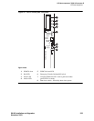
• TN2314 Processor circuit pack’s LEDs (after booting) on page 322
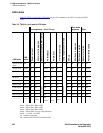
• Table , LED states, on page 324
LED boot sequence
The following describes the LED boot sequence:
TN2314 Processor circuit pack
When power is first applied to S8100, or when the system reboots, the LEDs on the TN2314 circuit pack
will light according to this sequence:
1 Every light on the TN2314 blinks in sequence (scrolls), from bottom to top. (The scrolling speed
fluctuates, depending on which test is being run.)
2 The 1
st
and 2
nd
tests run very fast. – The LEDs scroll quickly.
3 The 3
rd
and 4
th
tests run very slowly. – The LEDs scroll more slowly during these tests.
4 The LEDs scroll 17 times during the core testing phase.
5 All three LEDs double-blink when the tests finish.
Any other LEDs that are illuminated indicate an alarm or problem with S8100. For more information
about alarms, see Chapter 6, S8100 Windows 2000 Log Events and Alarms in Maintenance for the
Avaya S8100 Media Server with the Avaya G600 and CMC1 Media Gateways (555-233-149).
The emergency transfer LED is on if a reset 4 occurs or if power is cycled.


