


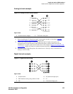

1Install and cable a G600 cabinet
Section II – Install telephones and make auxiliary connections
S8100 Installation and Upgrades 99
November 2003
Section II – Install telephones and make auxiliary
connections
This section describes procedures for installing and wiring telephones and making auxiliary connections.
Install and wire telephones and other equipment
NOTE:
Only 1 pair of wires is available for emergency transfer, and 1 pair of wires is available for
attendant console power.
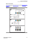
The wiring procedures are similar for most Avaya telephones and other equipment. This section provides
wiring examples for similar installation procedures. Actual wiring procedures may vary at each site.
The system can connect to any DTE terminal. The system can have RS-232 (or EIA-232) or DCP
interfaces.
As necessary, following sections of this chapter provide wiring pinouts for various port circuit packs.
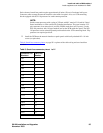
Also, Table 47, Leads for circuit packs and auxiliary equipment (pinout charts),
on page 281 has pinout
information for every port circuit pack.
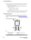
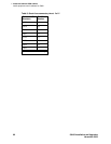
Punch-down information for common circuit packs is in Figure 73, Example MDF connections,
on page
380. This figure shows the colors of the punch-downs and is best viewed from CD-ROM or on-line.
After installing the hardware, the data for the system and telephone features can be administered. These
procedures are provided in Administrator’s Guide for Avaya Communication Manager (555-233-506).
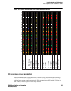
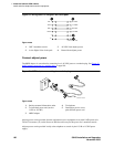
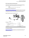
Telephone connection examples
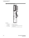
The 302C1 attendant console (AC) describes a typical telephone connection. This information is typical
of the 603E, 84xx (4-wire), and 94xx telephones. The AC always requires auxiliary (adjunct) power (-48
VDC). See Figure 23, Wiring 302C1 to a Digital Line circuit pack,
on page 100. Only 1 console can be
powered by the system through the auxiliary
(AUX) connector. The primary console should be powered
from the system so it has the same power failure backup as the system.
The maximum cabling distance for a cabinet-powered console is 350 feet (100 meters) using 24-AWG
(#5) (0.26-mm
2
) wire.
The general steps to connect a telephone are:
1 Choose a device to connect, such as a 302C1 attendant console.
2 Choose the port circuit pack, its carrier, and slot number (such as TN754C, Carrier A, Slot 06).
3 Choose a port circuit on the port circuit pack, such as Port 05.
4 Install cross-connect jumpers to wire the terminal to the port circuit pack. See Figure 23, Wiring
302C1 to a Digital Line circuit pack, on page 100. This pinout is for a 4-wire Digital Line circuit
pack.