


A Cable pinouts
Connector and cable diagrams – pinout charts
270 S8100 Installation and Upgrades
November 2003
Connector and cable diagrams – pinout charts
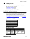
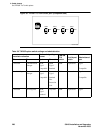
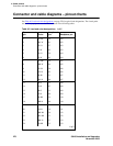
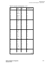
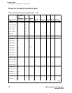
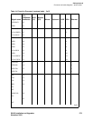
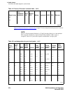
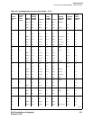
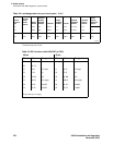
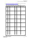
See Table 40, Lead and color designations, on page 270 for typical lead designations. The circuit packs
and auxiliary equipment are classified as shown in the following tables.
Table 40: Lead and color designations 1 of 2
Cross-connect
pin Color
Amphenol
pin Backplane pin
1W-BL26102
2BL-W01002
3W-O27103
4O-W02003
5W-G28104
6G-W03004
7W-BR29105
8 BR-W 04 005
9W-SL30106
10 SL-W 05 006
11 R-BL 31 107
12 BL-R 06 007
13 R-O 32 108
14 O-R 07 008
15 R-G 33 109
16 G-R 08 009
17 R-BR 34 110
18 BR-R 09 010
19 R-SL 35 111
20 SL-R 10 011
21 BK-BL 36 112
22 BL-BK 11 012
23 BK-O 37 113
24 O-BK 12 013
1 of 2