


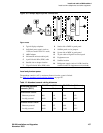

1Install and cable a G600 cabinet
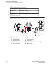
Connect external alarms and auxiliary connections
S8100 Installation and Upgrades 115
November 2003
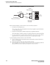
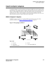
Emergency transfer and auxiliary power
NOTE:
Only 1 emergency transfer power panel and 1 auxiliary power connection are provided per
system.
Connect emergency transfer power and auxiliary power as shown in Table 16, Emergency transfer and
auxiliary power, on page 115. Auxiliary power includes power to an attendant console or adjunct device.
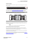
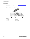
Telephone pin designations
Table 17, Port circuit pack and telephone pin designations, on page 115 provides pack and pin
designations.
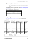
Table 16: Emergency transfer and auxiliary power
Power type Color AUX connector
Emergency Transfer Black-Blue XFER48 (Pin 36)
Blue-Black Ground (Pin 46)
Adjunct -48 VDC Brown-Yellow ACC48A (Pin 19)
Yellow-Brown Ground (Pin 44)
Table 17: Port circuit pack and telephone pin designations
Pin on
modular
plug
4-wire; 302C1,
8400-series,
603E, 9403, 9434
2-wire; 302C1,
8400-series, 603E,
9403, 9410, 9434
8510T BRI (with
adjunct speaker
phone)
Analog
station,
modem
Z3A1 & Z3A2
ADU, data
module
1TXT TXT
2 TXR T TXR
3PXT TXT R PXT
4TPXR
5RPXT
6PXR TXR PXR
7 -48VDC (-48VDC) (-48VDC)
8 GRD GRD GRD
circuit
pack
4-wire digital
(8 ports)
2-wire digital
(16 or 24 ports)
4-wire BRI Trunk
Side
Analog line
(16 or 24 ports)
Data Line
PX PBX transmit T Tip (A)
TX Terminal transmitR Ring (B)