


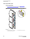

J Install and cable a CMC1 cabinet
Install equipment-room hardware for CMC1
372 S8100 Installation and Upgrades
November 2003
3 Connect the cable to the modem. See Appendix A, “Cable pinouts” for the pinout of the modem
cable.
4 Plug the modem power cord into an electrical outlet and turn on the modem.
Modem’s configuration and administration
on page 262 describes information about modem setup,
administration, settings, and testing.
Install equipment-room hardware for CMC1
See DEFINITY Communications System Generic 1 and Generic 3 Main Distribution Field Design (555-
230-630) for more information.
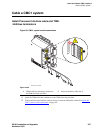
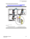
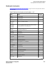
Cross-connect the cabinet to the MDF
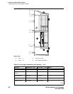
1 Cross-connect the port circuit packs to the CMC1 MDF. See Figure 73, Example MDF
connections, on page 380.
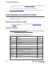
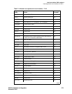
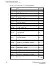
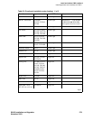
Allowed circuit packs
Table 61, Allowed circuit packs and circuit modules, on page 372 lists the circuit packs that can be used
with CMC1. (Table 62, Disallowed circuit packs and circuit modules,
on page 375 lists the circuit packs
that cannot be used with CMC1).
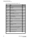
Table 61: Allowed circuit packs and circuit modules 1 of 3
Apparatus
code Name Allowed?
650A AC power unit Yes
NAA1 Fiber-Optic Cable Adapter circuit pack Yes
TN417 Auxiliary Trunk Yes
TN429/B/C/D Analog Direct Inward/Outward Dialing (DIOD) Central
Office Trunk
Yes
TN429C Analog Central Office Trunk Yes
TN429D Analog DIOD Trunk – Analog Loop Start Yes
TN433 Speech Synthesizer Yes
TN436B Direct Inward Dialing Trunk Yes
TN437B Tie Trunk Australia (future availability) Yes
TN438B Central Office Trunk Yes
TN439 Tie Trunk Yes
1 of 3