


MDS-D-SVJ3/SPJ3 Series Instruction Manual
2-8 Wiring of the peripheral control
2 - 35
2-8 Wiring of the peripheral control
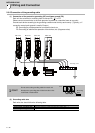
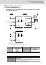
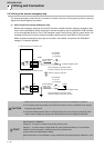
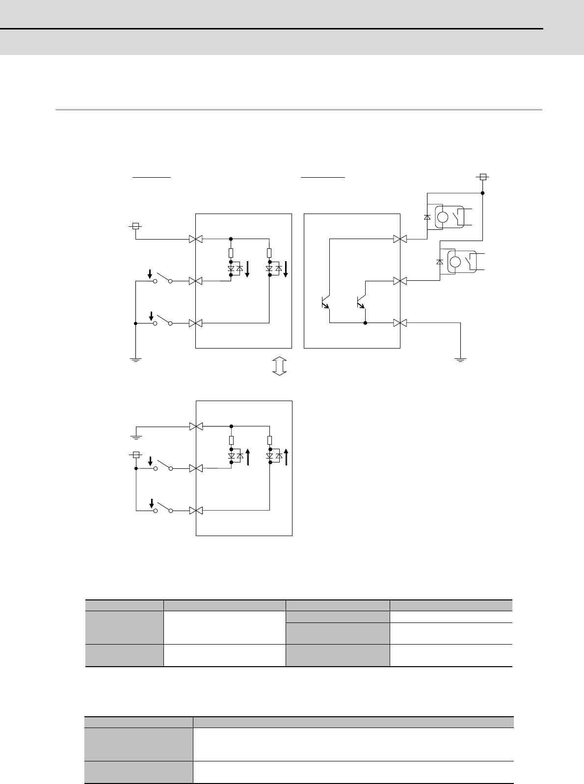
2-8-1 Wiring of the Input/output circuit
The input/output circuit to control the external signal such as external emergency stop input and relay
changeover signal output is wired.
The input/output circuit for each unit is as follows.
For a switch or relay to be wired, use a switch or relay that satisfies the input/output (voltage, current)
conditions.
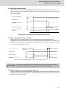
Input condition Output condition
Switch ON
18VDC to 25.2VDC
5mA or more
Output voltage 24VDC ±5%
Tolerable output
current Io
40mA or less
Switch OFF
4VDC or less
1mA or less
Interface name Selection example
For digital input signal
Use a minute signal switch which is stably contacted and operated even with low
voltage or current
<Example> OMRON: G2A, G6B type, MY type, LY type
For digital output signal
Use a compact relay operated with rating of 24VDC, 50mA or less.
<Example> OMROM: G6B type, MY type
3
15
CN9
CN9
24V
5
DICOM
20
EMGX
5.6k
19
DI
5.6k
13
DOCOM
MBR
MC
24V
(1)
(2)
5
DICOM
20
EMGX
5.6k
19
DI
5.6k
CN9
connector
connector
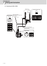
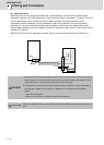
Input circuit Output circuit
Relay, etc.
Relay, etc.
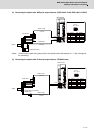
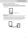
When DICOM is connected to 24V
Select the polarity of DICOM
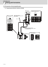
When DICOM is connected to 24G
connector
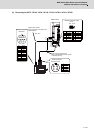
External emergency
stop
Proximity switch
(Note) For DICOM,
(1) the common input signal pattern (24V or 24G) is used.
(2) whichever polarity of the input can be used, however, the direction must be the same.