


5 - 44
5 Spindle Adjustment
MITSUBISHI CNC
5-4-2 Spindle control output (Spindle to NC)
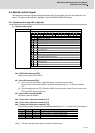
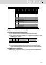
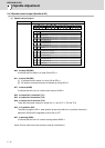
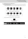
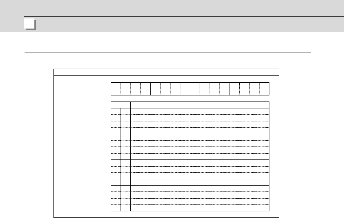
(1) Spindle control output 1
bit0. In ready ON (RDY)
It indicates that the status is in ready ON at RDY=1.
bit1. In servo ON (SRV)
[1] It indicates that the status is in servo ON at SRV=1.
[2] NC position command executes a followed up during SRV=0.
bit7. In alarm (ALMR)
It indicates that drive unit is in some alarm state at ALMR=1.
bit8. In torque limit 1 selection (TL1)
bit9. In torque limit 2 selection (TL2)
bitA. In torque limit 3 selection (TL3)
These are the answer outputs for torque limit 1, 2 and 3 (TL1, TL2 and TL3).
bitC. In in-position (INP)
The status changes to INP=1 when position droop exists within the in-position area set by
parameter SP024 (INP) regardless of serve ON or OFF.
bitF. In warning (WRN)
It indicates that drive unit is in some warning state at WRN=1.
(Note) The bits other than those above are used for maintenance.
FEDCBA9876543210
bit
0
1
2
3
4
5
6
7
8
9
A
B
C
D
E
F
RDY
SRV
-
-
-
-
-
-
RDYSRV
ALMR
TL1TL2TL3
TL2
TL1
TL3
-
-
ALMR
Details
Name Details
Spindle control output 1
In READY ON
In servo ON
(For maintenance)
In alarm
In torque limit 1 selection
(For maintenance)
(For maintenance)
(For maintenance)
In in-position
(For maintenance)
In warning
(For maintenance)
(For maintenance)
(For maintenance)
In torque limit 2 selection
In torque limit 3 selection