


5 - 27
MDS-D-SVJ3/SPJ3 Series Instruction Manual
5-2 Adjustment procedures for each control
5-2-6 Spindle C axis adjustment (For lathe system)
(1) Setting the gain
For spindle C axis speed loop gain, SP008 (speed loop gain 2), speed loop gain set 2, which consists of
SP009 (speed loop lead compensation 2), and SP010 (speed loop delay compensation 2), is used.
Thus, SP035 has to be set as follows. For position loop gain, set standard 33 to SP002 (position loop
gain, interpolation mode).
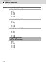
<Related servo parameters>
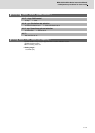
Set the spindle and interpolation axis.
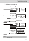
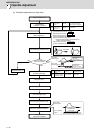
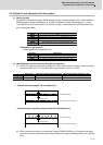
(2) Gain adjustment and accuracy test during C axis operation
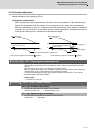
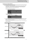
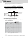
[1] Set the D/A output as follows during stopped in C axis mode (servo ON status) or when executing
cutting feed with G01 F20. Then check the droop fluctuation is within 10°/1000.
Offset is 2.5V.
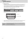
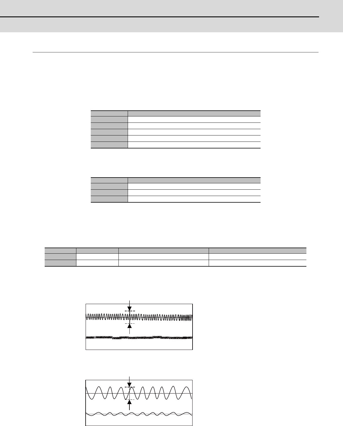
* Waveform during stopped in C axis (Reference)
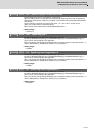
* Waveform when executing cutting feed with G01 F20 (Reference)
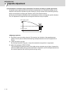
[2] When satisfactory accuracy is not secured, increase SP008 (VGN2) by 10 increments and adjust
so that the accuracy level meets the standard. Note that the maximum setting value is 150 x [inertia
ratio].
Parameter Setting value
SP002 33
SP008 SP005 setting value set in "5-2-1" (Initial setting value: 150)
SP009 1900
SP010 0
SP035 0200: Speed loop gain set 2 selection (validate bit9)
Parameter Setting value
SV003 Set the same value as spindle parameter "SP002"
SV004 Set it when using SHG control (when not using, set to "0" )
SV057 Set it when using SHG control (when not using, set to "0" )
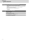
Output name Setting value (Setting parameter: Value) Magnification (Setting parameter: Value)
CH1 output Position droop SP125 : 60 SP127 = 10000 (0.01°/V)
CH2 output Current command SP126 : 2 SP128 = 1000 (10%/V)
Ch1: Position
droop
Ch2: q axis current command
0
0
0.010° or less
Ch1: Position droop
Ch2: q axis current command
0
0
0.010° or less