


6 - 15
MDS-D-SVJ3/SPJ3 Series Instruction Manual
6-3 Troubleshooting
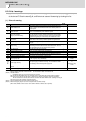
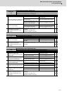
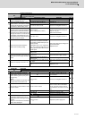
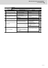
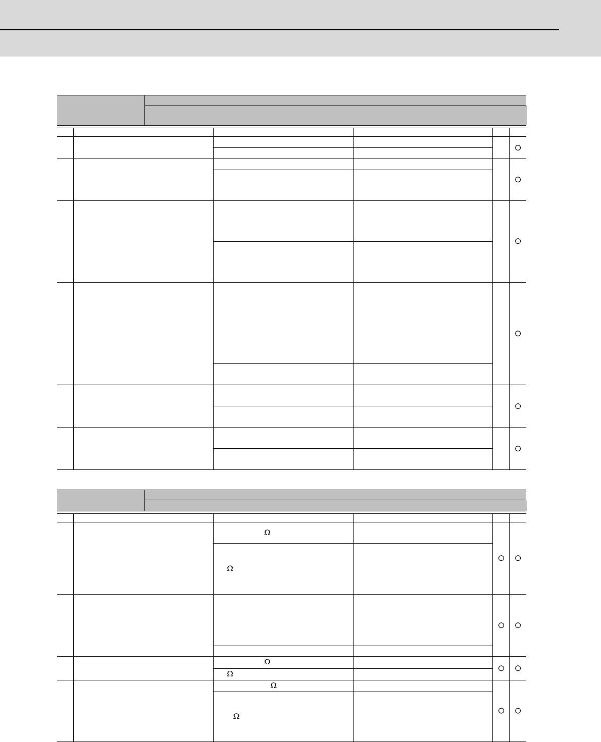
Alarm No.
23
Excessive speed error
A difference between the speed command and speed feedback was continuously exceeding 50 r/min for
longer than the setting time.
Investigation details Investigation results Remedies SV SP
1
Check the U, V and W wiring connect-
ed to the spindle drive unit.
The wires are not correctly connected. Correctly connect.
The wires are correctly connected. Check the investigation item No. 2.
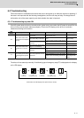
2
Check the spindle parameter SP020,
SP026, SP027, from SP057 to SP064
and spindle specification parameters
from slimit1 to slimit4 setting value.
The correct values are not set. Correctly set.
The correct values are set. Check the investigation item No. 3.
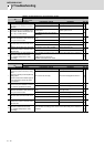
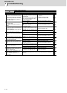
3
Measure the acceleration/ decelera-
tion time from 0 to the point where the
spindle speed reaches its maximum.
If the alarm occurs when forward run is
changed to reverse run, measure the
acceleration/ deceleration time from
the forward to reverse. Also measure it
from the reverse to forward.
12sec or more.
(SP117 setting value or more.)
Increase the spindle acceleration/de-
celeration time constant setting val-
ue(sp_t1 to sp_t4).
Reduce the load inertia.
Less than 12sec. Check the investigation item No. 4.
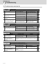
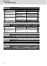
4
Check the load amount when the
alarm occurred during cutting.
The speed deterioration due to load
amount has exceeded the tolerable
range which is determined by the pa-
rameter SP096.
-If SP096 is set to 0, it is regarded as
85%. Thus a speed of 85% of the ma-
chining speed or faster will be the tol-
erable speed.
Reduce the cutting load to mitigate the
speed deterioration.
Replace the tool.
The load amount is within the SP096
setting value.
Check the investigation item No. 5.
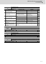
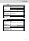
5
Check the fluctuation of the input volt-
age into the power supply unit with a
tester.
Voltage drop during acceleration is
200V or less
Review the power supply capacity.
Voltage drop during acceleration is
200V or more
Check the investigation item No.6.
6 Check the capacity of the drive unit.
The capacity does not satisfy the mo-
tor output.
Change the capacity to the selected
one.
The capacity satisfies the motor out-
put.
Replace the unit.
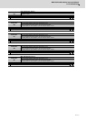
Alarm No.
24
Grounding
The motor power cable is in contact with FG (Frame Ground).
Investigation details Investigation results Remedies SV SP
1
Measure the insulation across the
power cables (U,V,W) for connected
motors and the ground. (Carry out a
megger test.)
(Note)
When the insulation is measured, dis-
connect wires from the drive unit.
Less than 1M .
The motor or power cable may be
ground faulted.
1M or more.
Check the investigation item No. 2.
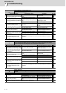
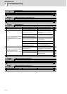
2
Has oil come in contact with the motor
or power cable?
Oil has come in contact.
Take measures so that oil does not
come in contact. Check the motor's
cannon connector and the inside of
the terminal box, and clean as neces-
sary.
Oil has not come in contact. Check the investigation item No. 3.
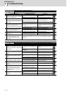
3 Measure the insulation again.
Less than 1M .
Replace the motor or cable.
1M or more.
Check the investigation item No. 4.
4
Measure the resistance across the U,
V, W phase terminals of the servo/
spindle drive unit and the ground with
a tester.
(Note) Do not measure the insulation
as the unit is damaged.
Less than 100k .
Replace the drive unit.
100k or more.
Replace the power supply unit.