


6 - 4
6 Troubleshooting
MITSUBISHI CNC
6-2 Protective functions list of units
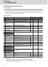
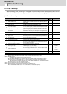
6-2-1 List of alarms
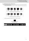
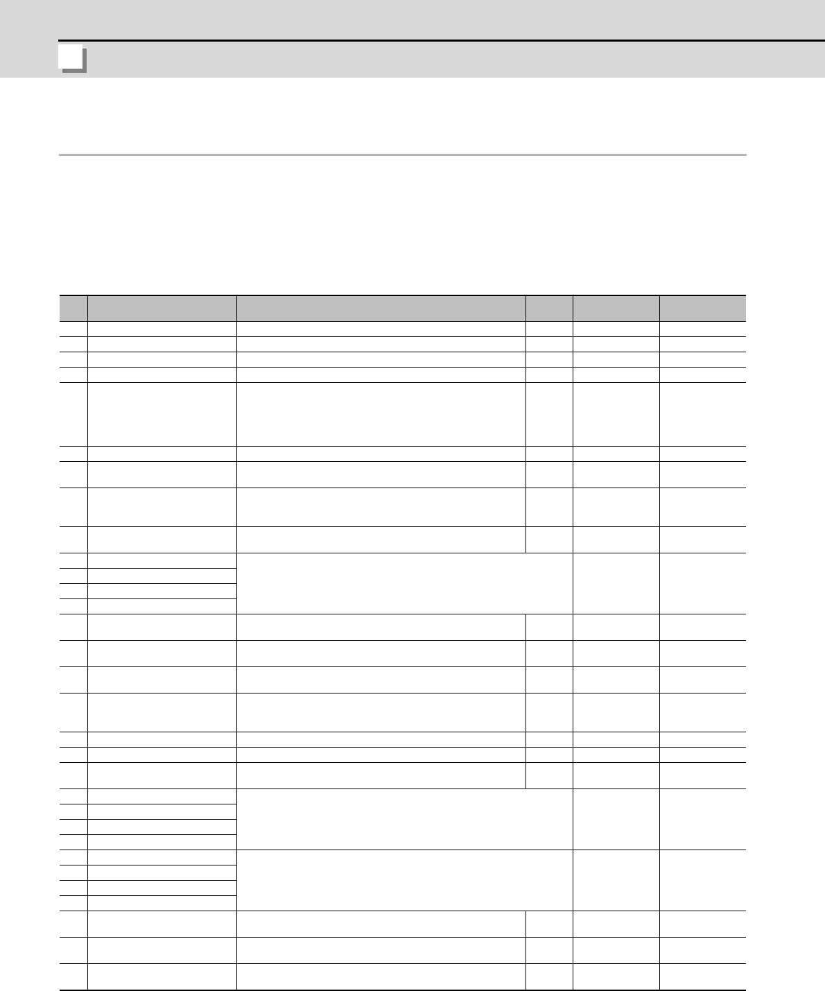
When an alarm occurs, the servo drive unit will make the motor stop by the deceleration control or dynamic
brake. The spindle drive unit will coast to a stop or will decelerate to a stop. At the same time, the alarm No.
will appear on the NC monitor screen and with the LEDs on the front of the drive unit. Check the alarm No.,
and remove the cause of the alarm by following this list.
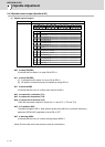
(1) Drive unit alarm
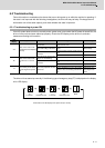
(Note1) Definitions of terms in the table are as follows.
Main side detector: Detector connected to CN2 Sub side detector: Detector connected to CN3
(Note2) Resetting methods
NR: Reset with the NC RESET button. This alarm can also be reset with the PR and AR resetting conditions.
PR: Reset by turning the NC power ON again. This alarm can also be reset with the AR resetting conditions.
When the control axis is removed, this alarm can be reset with the NC RESET button. (Excluding alarms 32 and 37.)
AR: Reset by turning the servo drive unit power ON again.
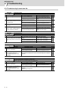
No. Name Details
Reset
method
Servo
stop method
Spindle
stop method
10
Insufficient voltage A drop of bus voltage was detected in main circuit. PR Dynamic stop Coast to a stop
11
Axis selection error The axis selection rotary switch has been incorrectly set. AR Initial error Initial error
12
Memory error 1 A hardware error was detected during the power ON self-check. AR Initial error Initial error
13
Software processing error 1 An error was detected for the software execution state. PR Dynamic stop Coast to a stop
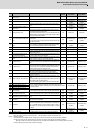
16
Initial magnetic pole position de-
tection error
In the built-in motor which uses the absolute position detector, the
servo ON has been set before the magnetic pole shift amount is
set.
The magnetic pole position, detected in the initial magnetic pole
position detection control, is not correctly set.
PR Dynamic stop Coast to a stop
17
A/D converter error A current feedback error was detected. PR Dynamic stop Coast to a stop
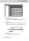
18
Main side detector:
Initial communication error
An error was detected in the initial communication with the motor
side detector.
PR Initial error Initial error
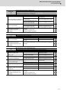
19
Detector communication error in
synchronous control
An error of the shared detector on the machine side was detected
on the secondary axis of the speed command synchronization
control.
PR Dynamic stop -
1A
Sub side detector:
Initial communication error
An error was detected in the initial communication with the ma-
chine side detector.
PR Initial error Initial error
1B
Sub side detector: Error 1
An error was detected by the detector connected to the machine side.
The error details are different according to the detector type. Refer to "Detec-
tor alarm" for details.
Dynamic stop Coast to a stop
1C
Sub side detector: Error 2
1D
Sub side detector: Error 3
1E
Sub side detector: Error 4
1F
Sub side detector:
Communication error
An error was detected in the communication with the machine
side detector.
PR Dynamic stop Coast to a stop
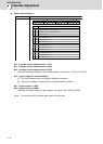
21
Sub side detector no signal 2
In the machine side detector, ABZ-phase feedback cannot be re-
turned even when the motor moves.
PR Dynamic stop Coast to a stop
22
Detector data error
An error was detected in the feedback data from the position de-
tector.
AR Dynamic stop -
23
Excessive speed error
The state that there is a difference between the actual speed and
command speed continued for longer than the excessive speed
deviation timer setting.
NR - Coast to a stop
24
Grounding The motor power cable is in contact with FG (Frame Ground). PR Dynamic stop Coast to a stop
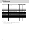
25
Absolute position data lost The absolute position data was lost in the detector. AR Initial error -
26
Unused axis error
In the multiaxis drive unit, there is an axis set to free, and the other
axis detected a power module error.
PR Dynamic stop Coast to a stop
27
Sub side detector: Error 5
An error was detected by the detector connected to the machine side.
The error details are different according to the detector type. Refer to "Detec-
tor alarm" for details.
Dynamic stop Coast to a stop
28
Sub side detector: Error 6
29
Sub side detector: Error 7
2A
Sub side detector: Error 8
2B
Main side detector: Error 1
An error was detected by the detector connected to the motor side.
The error details are different according to the detector type. Refer to "Detec-
tor alarm" for details.
Dynamic stop Coast to a stop
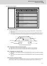
2C
Main side detector: Error 2
2D
Main side detector: Error 3
2E
Main side detector: Error 4
2F
Main side detector:
Communication error
An error was detected in the communication with the motor side
detector.
PR Dynamic stop Coast to a stop
30
Over regeneration
Over-regeneration level exceeded 100%. The regenerative resis-
tor is overloaded.
PR Dynamic stop Coast to a stop
31
Overspeed The motor speed exceeded the allowable speed. PR
Deceleration stop
enabled
Deceleration stop
enabled