


5 - 39
MDS-D-SVJ3/SPJ3 Series Instruction Manual
5-4 Spindle control signal
5-4 Spindle control signal
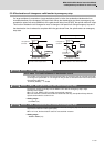
The sequence input/output signals exchanged between the NC and spindle drive unit are explained in this
section. The status of each signal is displayed on the NC SPINDLE MONITOR screen.
5-4-1 Spindle control input (NC to Spindle)
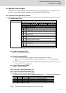
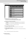
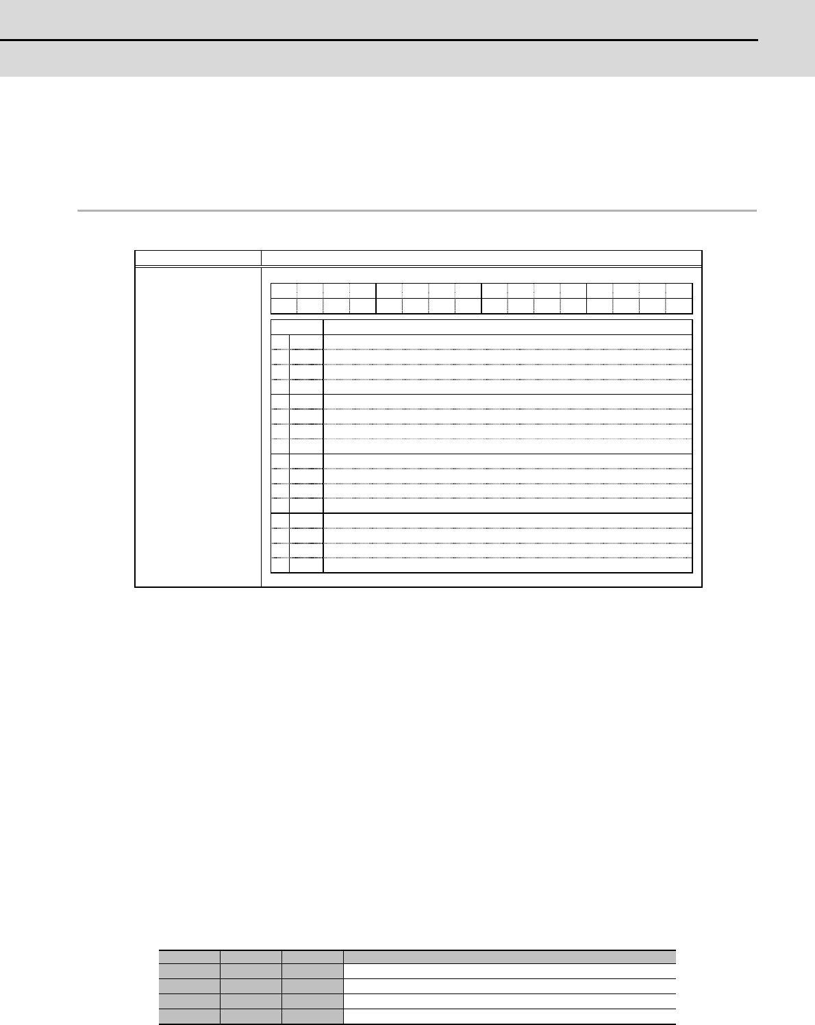
(1) Spindle control input 1
bit0. READY ON command (RDY)
Status turns to ready ON at RDY=1.
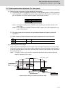
bit1. Servo ON command (SRV)
[1] Drive unit turns ON at SRV=1 (gate ON status), and rotation control starts.
Plus or minus of the rotation direction is determined depending on +/- of the NC command
FΔT.
[2] Servo immediately turns OFF (SON=0) at SRV=0 during rotation control. Drive unit also turns
OFF (gate OFF status) at this time.
bit7. Alarm reset command (ALMR)
NR alarm is reset at ALMR=1.
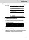
bit8. Torque limit 1 selection command (TL1)
bit9. Torque limit 2 selection command (TL2)
bitA. Torque limit 3 selection command (TL3)
The following 4 types of torque limit are available depending on TL1, TL2 and TL3 bit combinations.
(Note) The ratio to motor short time rated torque (load meter 100%) is indicated in %.
(Note) The bits other than those above are used for maintenance.
TL3 TL2 TL1 Torque limit value
0 0 1 Torque limit value (%) set with parameter SP065
0 1 0 Torque limit value (%) set with parameter SP066
0 1 1 Torque limit value (%) set with parameter SP067
1 0 0 Torque limit value (%) set with parameter SP068
Name Details
Spindle control input 1
F E D C B A 9 8 7 6 5 4 3 2 1 0
TL3 TL2 TL1
ALMR
SRV RDY
bit Details
0
RDY
READY ON command
1
SRV
Servo ON command
2
- (For maintenance)
3
-
(For maintenance)
4
-
(For maintenance)
5
-
(For maintenance)
6
-
(For maintenance)
7
ALMR
Alarm reset command
8
TL1
Torque limit 1 selection command
9
TL2
Torque limit 2 selection command
A
TL3
Torque limit 3 selection command
B
-
(For maintenance)
C
-
(For maintenance)
D
-
(For maintenance)
E
-
(For maintenance)
F
-
(For maintenance)