


6 - 30
6 Troubleshooting
MITSUBISHI CNC
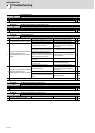
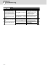
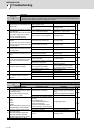
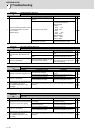
Alarm No.
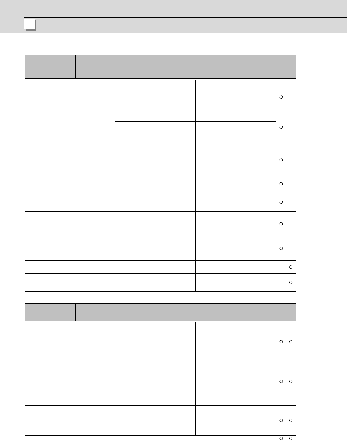
51
Overload 2
Current command of more than 95% of the unit's max. current was being continuously given for longer than
1 second in a servo system. In a spindle system, current command of more than 95% of the motor's max.
current was being continuously given for longer than 1 second.
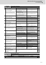
Investigation details Investigation results Remedies SV SP
1
Did the alarm occur immediately after
READY ON?
The alarm occurred after ready ON
before operation starts.
Investigate item 2.
The alarm occurred after normal oper-
ation.
Investigate item 5.
2
Check that the PN voltage is supplied
to the drive unit.
MDS-D-SVJ3 Series is not connected
to the power supply unit, so investi-
gate item 3 for MDS-D-SVJ3.
[1] Is the CHARGE lamp ON?
The CHARGE lamp becomes dark.
L+ or L- screw was loosened.
Increase the capacity of power supply.
Tighten the L+ and L- screws.
Approx. 300V is correctly supplied. Investigate item 3.
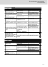
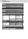
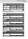
3
Check the motor power cable (U, V, W
phases).
[1] The power cable is not connected.
[2] Is the cable connected to the motor
for another axis?
The connections are incorrect.
Connected to the incorrect axis.
Connect correctly.
The connections are correct. Investigate item 4.
4
Check the detector cable connection.
[1] Is the cable connected to the motor
for another axis?
The connections are incorrect. Connect correctly.
The connections are correct. Investigate item 5.
5
Check whether the machine has col-
lided.
The machine has collided.
Check the machining program and
soft limit settings.
The machine has not collided. Investigate item 6.
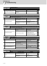
6
Check whether the current value on
the NC Servo Monitor screen is satu-
rated during acceleration/decelera-
tion.
The current is saturated during accel-
eration/deceleration.
Increase the acceleration/ decelera-
tion time constant.
The current value during acceleration/
deceleration is appropriate.
Investigate item 7.
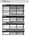
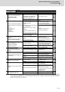
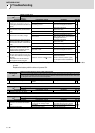
7 Check the detector Feedback.
The Feedback signal is abnormal.
- The droop does not stabilize.
Replace the detector.
(With the absolute position system,
the zero point must be established.)
The Feedback signal is normal. Replace the drive unit.
8 Check the load meter value.
The value is large. Lower the load.
The value is normal. Investigate item 9.
9
Check the PLG output waveform.
For TS5690, waveform cannot be
checked.
There is a problem. Adjust the PLG output waveform.
Normal Replace the drive unit.
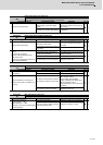
Alarm No.
52
Excessive error 1
A difference between the actual and theoretical motor positions during servo ON exceeded the setting val-
ue.
Investigation details Investigation results Remedies SV SP
1
The load inertia is large.
The unbalance torque in the Z (gravi-
ty) direction is high.
An excessive workpiece or tool is
mounted on the spindle.
The load inertia is excessive.
[1] Lower the machine weight applied
to the servo motors (by the unbalance
torque).
[2] Lower the weight of the workpiece.
The load inertia is normal. Investigate item 2.
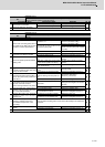
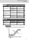
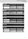
2
Check the excessive error detection
width.
Servo
SV053
Spindle
SP023 (Interpolation, spindle synchro-
nization)SP053 (Non-interpolation)
The excessive error detection width is
too small.
Servo standard value:
SV053 ={RAPID/(60*PGN1)}/2
Spindle standard value:
No alarm is set at SP023 =120:0
SP053 =motor max. speed×6/PGV/2
Set appropriate values.
Appropriate values are set. Investigate item 3.
3
Check the position detector polarity.
SV017/bit4 (Servo)
SP017/bit4 (Spindle: position FB)
SP017/bit0 (Spindle: speed FB)
#3106/bit7 (Synchronous tap control)
The polarity is reversed. Correctly set the parameters.
Normal. Investigate item 4.
4 Check the alarm No. "51" items.