


4 - 58
4 Servo Adjustment
MITSUBISHI CNC
4-8 Servo control signal
The sequence input/output signals exchanged between the NC and servo drive unit are explained in this
section. The status of each signal is displayed on the NC SERVO MONITOR screen.
4-8-1 Servo control input (NC to Servo)
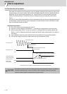
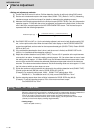
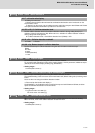
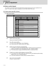
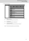
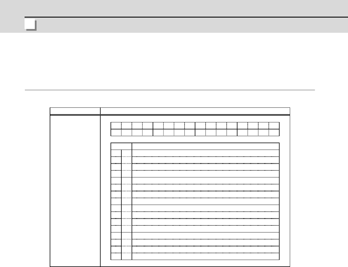
(1) Servo control input 1
bit0. READY ON command (RDY)
Status turns to ready ON at RDY=1.
bit1. Servo ON command (SRV)
[1] Drive unit turns ON at SRV=1 (servo ON status).
[2] Drive unit turns OFF at SRV=0 (servo OFF status).
bit4. Position loop gain changeover command (KPM)
[1] The position loop gain (SV049/SV050/SV058) for spindle synchronous (synchronous
tapping, synchronous control with spindle C-axis, etc.) is selected at KPM=1.
[2] The normal position loop gain (SV003/SV004/SV057) is selected at KPM=0.
bit6. Excessive error detection width changeover command (EOM)
[1] The excessive error width (SV053) for the special control (initial absolute position setting,
stopper control, etc.) is selected at EOM =1.
[2] The normal excessive error width (SV023) is selected at EOM =0.
bit7. Alarm reset command (ALMR)
NR alarm is reset at ALMR=1.
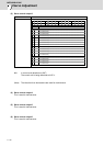
FEDCBA9876543210
bit
0
1
2
3
4
5
6
7
8
9
A
B
C
D
E
F
RDY
SRV
-
-
KPM
-
EOM
IL1
-
-
-
-
-
-
-
RDYSRV
KPMEOM
ALMR
IL1
ALMR
Details
Name Details
Servo control input 1
READY ON command
Servo ON command
(For maintenance)
Position loop gain changeover command
Excessive error detection width changeover command
Alarm reset command
Current limit selection command
(For maintenance)
(For maintenance)
(For maintenance)
(For maintenance)
(For maintenance)
(For maintenance)
(For maintenance)
(For maintenance)
(For maintenance)