


1 - 27
MDS-D-SVJ3/SPJ3 Series Instruction Manual
1-5 Installation of the spindle detector
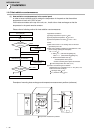
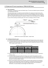
(3) Details for PLG installation diagnosis
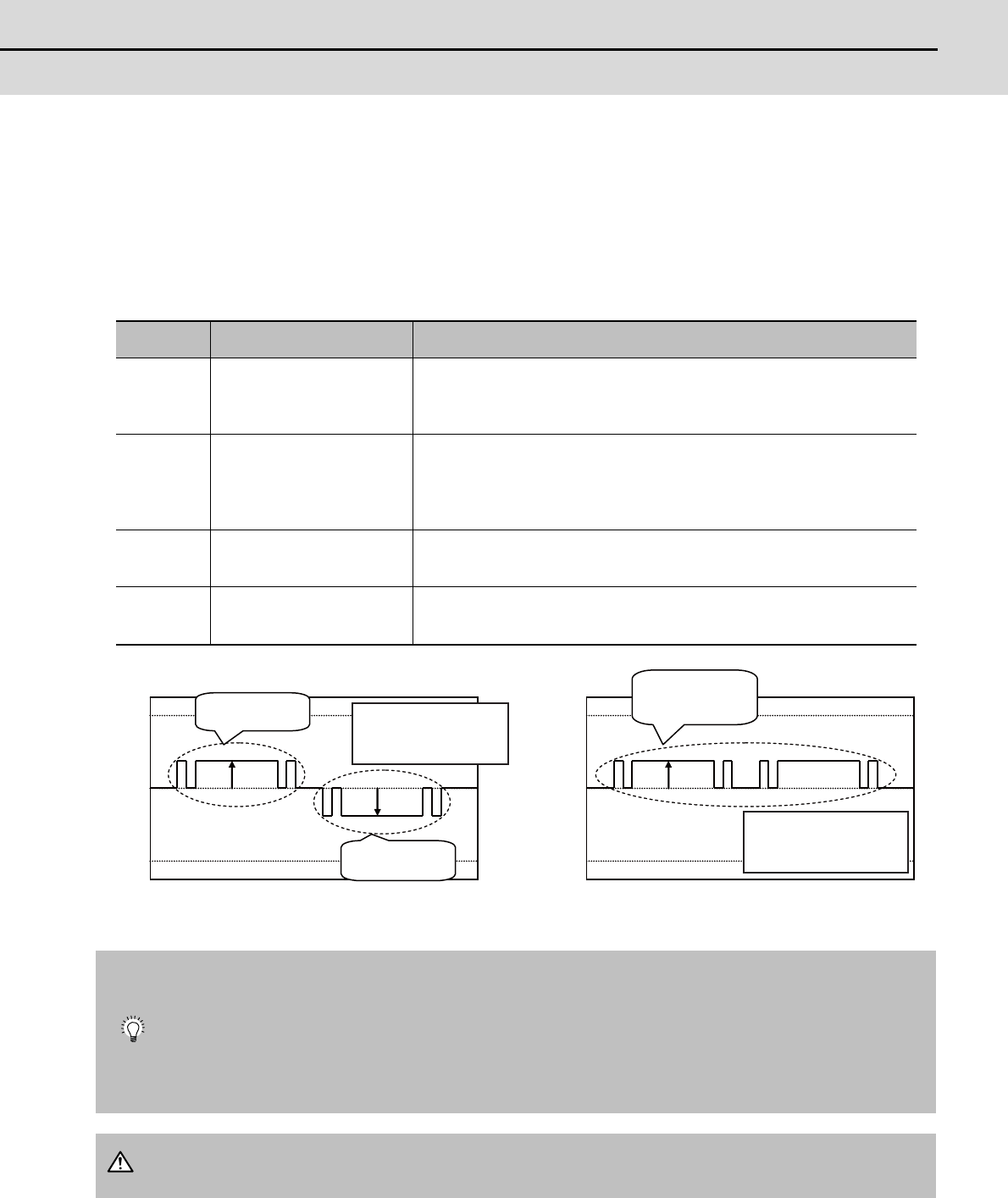
Installation error judgment of the adjustment-free PLG can be checked using the D/A output of the
spindle drive unit. The setting numbers of D/A output are shown below. For the output waveform, 2.5V
represents a normal state and +1V or -1V of the normal state represents an abnormal state.
*Set the D/A output numbers to the spindle parameters "#13125(SP125)" and "#13126(SP126)".
Because the D/A output of the drive unit is 2ch, perform the check for both at the motor end and spindle
end in full closed mode.
(4) Related alarms
There is no alarm related to the installation accuracy diagnosis for PLG detector.
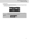
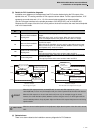
D/A output
No.
Details Description
120
Motor end PLG installation
Gap diagnosis
The result of the quality judgement for the gap of the motor end PLG is
output.
When the gap is good, =2.5V is output. When the gap is excessive,
=2.5+1V is output and when the gap is too small, =2.5-1V is output.
121
Motor end PLG installation
All errors diagnosis
The result of the quality judgement for the installed position of the motor
end PLG is output.
When the sensor installation is good, =2.5V is output. When sensor instal-
lation is incorrect (such as a center deviation between a sensor and gear,
and Z-phase error), =2.5+1V is output.
122
Spindle end PLG installation
Gap diagnosis
The result of the quality judgement for the gap of the spindle end PLG is
output.
The output procedure is the same as that of motor end PLG.
123
Spindle end PLG installation
All errors diagnosis
The result of the quality judgement for the installed position of the spindle
end PLG is output.
The output procedure is the same as that of motor end PLG.
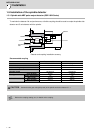
When the D/A output parameter "#13125(SP125)" is set to 120(=D/A output of ch1), and
"#13126(SP126)" is set to 121(=D/A output of ch2), the check is performed at the motor end detector.
When the D/A output of ch1 is 2.5V and ch2 is 3.5V(=2.5+1V), for example, the gap is normal,
however, the center deviation (offset) between a sensor and gear occurs, so check again after the
sensor installed position is finely adjusted. Adjust until the two D/A outputs finally become 2.5V during
spindle rotation.
When the sensor installed position is finely adjusted, adjust after the power of the drive unit is turned
OFF.
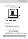
5.0V
2.5V
0.0V
5.0V
2.5V
0.0V
+1V
-1V
+1V
The gap is excessive
Waveform example
when the gap is not good
The gap is too small
Waveform example
when all results of the diagnosis are not good
Offset fault
Gap fault
Z-phase error
The gap is good when the
waveform is constantly at
2.5V during the rotation.
The installation is good when
the waveform is constantly at
2.5V during the rotation.
POINT
CAUTION