


MDS-D-SVJ3/SPJ3 Series Instruction Manual
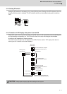
2-8 Wiring of the peripheral control
2 - 49
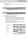
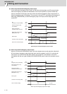
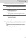
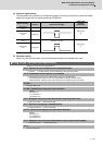
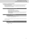
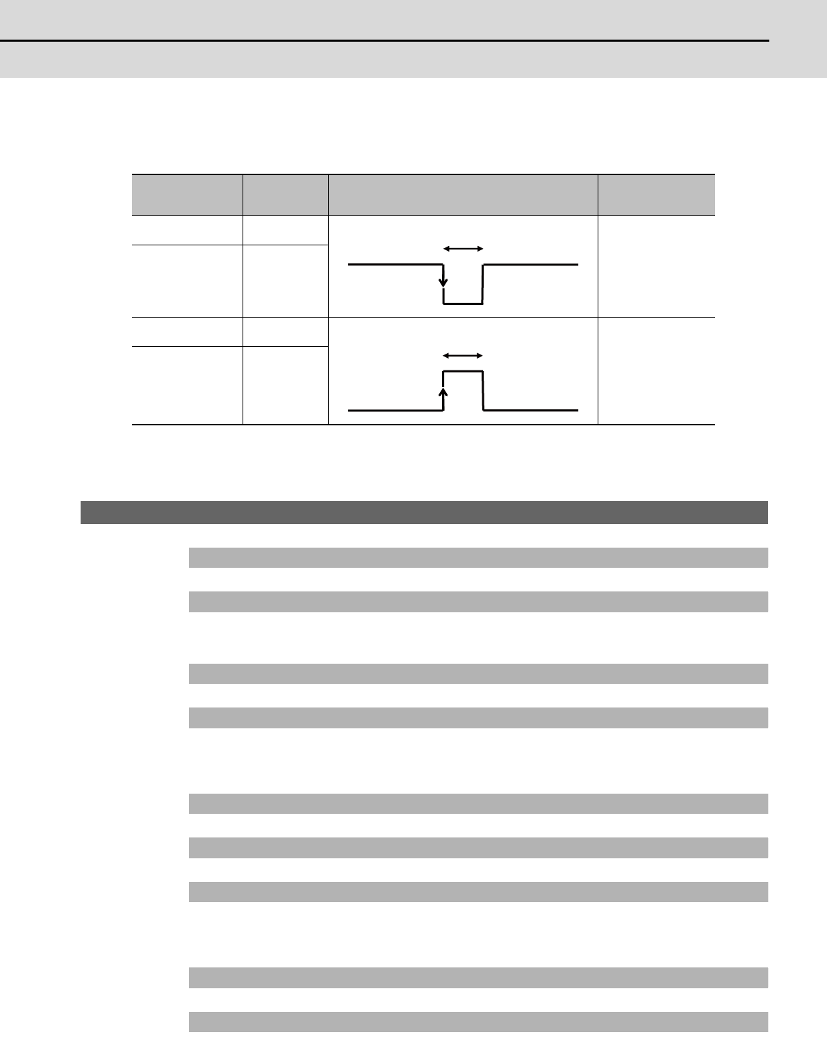
(3) Detection signal polarity
The table below is the polarities of the detections signals. According to the polarity, select the enable
edge of the signals with the spindle parameter (SP225/bit5).
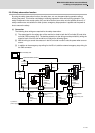
(4) Parameter setting
When using the proximity switch, set the following parameters to the spindle to be used.
【#3106】 zrn_typ Zero point return specifications
Select the zero point return specification.
bit F : Spindle zero point detection with contactless switch
0: Normal 1: Enable spindle zero point detection using proximity switch
bit E : Interpolation mode selection in orientation
0: Interpolation mode (Use the interpolation mode gain "SP002 PGN".)
1: Non-interpolation mode (Use the non-interpolation mode gain "SP001 PGV")
Select this when vibration occurs since the gain is too high during the orientation.
bit D-B :
Not used. Set to "0".
bit A-9 : Spindle/C axis zero point return direction
bitA,9=
00: Short-cut
01: Forward run
10: Reverse run
bit 8 : Designate zero point return/deceleration stop of spindle/C axis
0: Zero point return 1: Deceleration stop
bit 7 : Synchronous tapping command polarity
0: Forward direction 1: Reverse direction
bit 6-5 : Synchronous tapping zero point return direction
bit 6,5=
00: Short-cut
01: Forward run
10: Reverse run
bit 4 : Designate zero point return/deceleration stop in synchronous tapping
0: Zero point return 1: Deceleration stop
bit 3 :
Not used. Set to "0".
Sensor operation
Enable
detection
Drive unit input signal polarity
(CN9 connector 20pin)
Enable edge
selection
(SP225/bit5)
Normal open
(NO)
Rising part
Falling edge
(0)
Normal close
(NC)
Falling part
Normal open
(NO)
Rising part
Rising edge
(1)
Normal close
(NC)
Falling part
Detection of enable
Detection of enable