


5 - 41
MDS-D-SVJ3/SPJ3 Series Instruction Manual
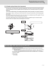
5-4 Spindle control signal
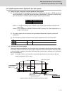
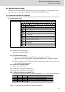
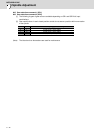
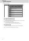
(4) Spindle control input 4
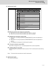
bit0. Spindle control mode selection command 1 (SC1)
bit1. Spindle control mode selection command 2 (SC2)
bit2. Spindle control mode selection command 3 (SC3)
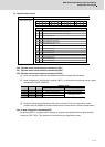
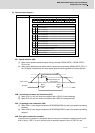
[1] Drive unit operation mode can be selected with the bit correspondences below.
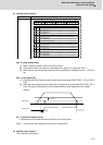
[2] Mode changeover is valid during in-position (INP=1) or other than during droop cancel / phase
compensation (DCSL=PCMP=0).
(Note) When selecting bits other than above, control mode error (4E) occurs.
[3] Continuity cannot be guaranteed for the value of position FB in non-interpolation mode.
(Position may be skipped for multiple rotations due to droop cancel or phase compensation.)
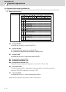
bit4. In gear changeover command (GKC)
By inputting GKC=1, the gear ratio is changed to the gear ratio specified with the gear selection
command (GR1, GR2). This command is invalid during the interpolation mode.
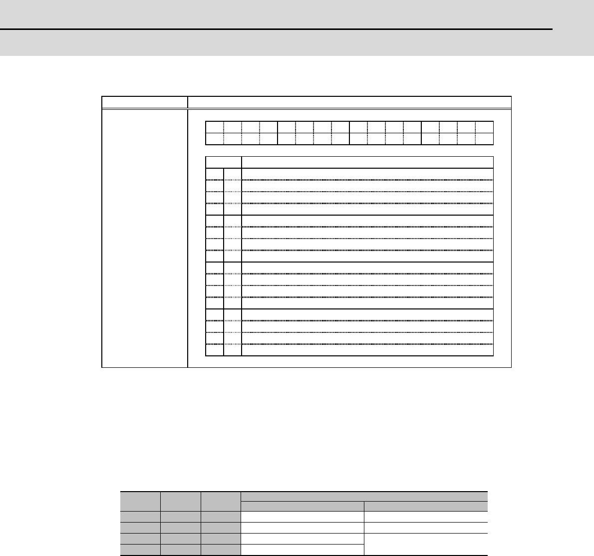
SC3 SC2 SC1
Operation mode
Conventional method New method
0 0 0 Speed/orientation control Non interpolation control
0 0 1 Spindle synchronization Spindle synchronization
0 1 0 C-axis control
Interpolation control
1 0 0 Synchronous tapping control
FEDCBA9876543210
bit
0
1
2
3
4
5
6
7
8
9
A
B
C
D
E
F
-
-
-
-
-
-
-
SC2
GKCGR2
-
-
GR1
SC3 SC1
SC2
GKC
GR2
GR1
SC3
SC1
-
Details
Name Details
Spindle control input 4
Spindle control mode selection command 1
(For maintenance)
Gear selection command 1
(For maintenance)
(For maintenance)
(For maintenance)
(For maintenance)
Gear changeover command
Spindle control mode selection command 2
Spindle control mode selection command 3
Gear selection command 2
(For maintenance)
(For maintenance)
(For maintenance)
(For maintenance)
(For maintenance)