


6 - 6
6 Troubleshooting
MITSUBISHI CNC
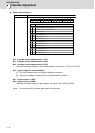
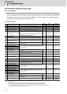
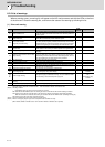
(Note1) Definitions of terms in the table are as follows.
Main side detector: Detector connected to CN2 Sub side detector: Detector connected to CN3
(Note2) Resetting methods
NR: Reset with the NC RESET button. This alarm can also be reset with the PR and AR resetting conditions.
PR: Reset by turning the NC power ON again. This alarm can also be reset with the AR resetting conditions.
When the control axis is removed, this alarm can be reset with the NC RESET button. (Excluding alarms 32 and 37.)
AR: Reset by turning the servo drive unit power ON again.
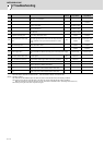
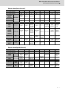
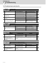
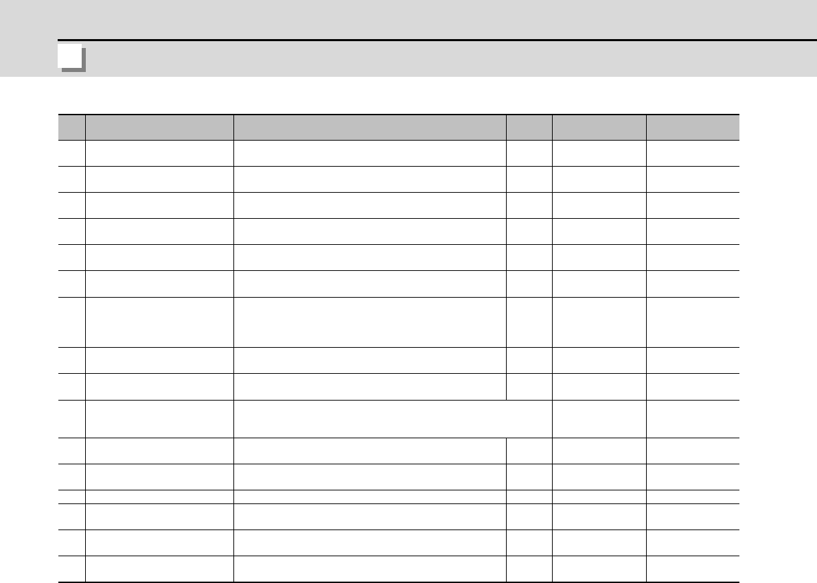
No. Name Details
Reset
method
Servo
stop method
Spindle
stop method
54 Excessive error 3
There was no motor current feedback when the alarm "Exces-
sive error 1" was detected.
NR Dynamic stop Coast to a stop
56 Commanded speed error
In the C-axis control mode, excessive speed error was detect-
ed.
NR -
Deceleration stop
enabled
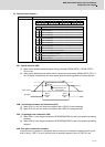
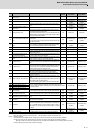
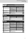
58 Collision detection 1: G0
A disturbance torque exceeded the allowable value in rapid
traverse modal (G0).
NR
Maximum capacity
deceleration stop
-
59 Collision detection 1: G1
A disturbance torque exceeded the allowable value in the cut-
ting feed modal (G1).
NR
Maximum capacity
deceleration stop
-
5A Collision detection 2
A current command with the maximum drive unit current value
was detected.
NR
Maximum capacity
deceleration stop
-
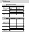
5B
Safety observation: Command-
ed speed monitoring error
A commanded speed exceeding the safe speed was detected
in the safety observation mode.
PR
Deceleration stop
enabled
Deceleration stop
enabled
5D
Safety observation: Door state
error
The door state signal input in the NC does not coincide with the
door state signal input in the drive unit in the safety observation
mode. Otherwise, door open state was detected in normal
mode.
PR
Deceleration stop
enabled
Deceleration stop
enabled
5E
Safety observation: Speed feed-
back monitoring error
A motor speed exceeding the safe speed was detected in the
safety observation mode.
PR
Deceleration stop
enabled
Deceleration stop
enabled
5F External contactor error A contact of the external contactor is welding. NR
Deceleration stop
enabled
Deceleration stop
enabled
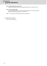
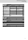
60
to
77
Power supply alarm
The power supply unit detected an error.
The error details are different according to the connected power supply
unit.
Dynamic stop Coast to a stop
80 Main side detector cable error
The cable type of the motor side detector cable is for rectangu-
lar wave signal.
AR Initial error -
81 Sub side detector cable error
The cable type of the machine side detector cable does not co-
incide with the detector type which is set by the parameter.
AR Initial error -
87 Drivers communication error The communication frame between drive units was aborted. PR Dynamic stop Coast to a stop
88 Watchdog
The drive unit does not operate correctly.
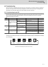
"888" is displayed for MDS-D-SVJ3/SPJ3.
AR Dynamic stop Coast to a stop
8A
Drivers communication data er-
ror 1
The communication data 1 between drivers exceeded the tol-
erable value in the communication between drive units.
PR Dynamic stop Coast to a stop
8B
Drivers communication data er-
ror 2
The communication data 2 between drivers exceeded the tol-
erable value in the communication between drive units.
PR Dynamic stop Coast to a stop