


1 - 23
MDS-D-SVJ3/SPJ3 Series Instruction Manual
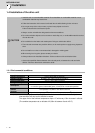
1-5 Installation of the spindle detector
1-5-2 Spindle side PLG serial output detector (TS5690, MU1606 Series)
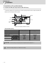
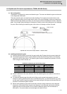
(1) Part configuration
The detector is configured of a sensor and detection gear. The sensor and detection gear must be used
in the designated combination.
These are precision parts, and require care when handling. Do not apply an excessive force on the
sensor's detection surface, as this could result in faults. Do not pull and apply a load on the lead wires.
Make sure that foreign matters (iron chips, etc.) do not get on the sensor's detection surface or detection
gears. If any foreign matter should get on these parts, carefully remove while taking care not to damage
the parts. When handling the detection gears, take care not to damage or deform the teeth.
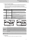
Spindle side PLG serial output detector TS5690 Series
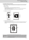
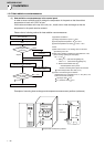
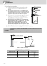
(2) Installing the detection gears
[1] Install the detection gears so that the first gear's teeth side (Z phase) face the sensor's lead side.
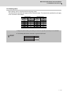
[2] The detection gears and shaft or sleeve should be fixed with shrink fitting. Refer to the following
table for the shrink fitting values. The detection gears should be heated evenly between 120 and
150°C using an electric furnace, etc.
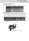
Guideline for detection gear shrink fitting values
[3] Keep the deflection of the outer diameter, when the detection gears are installed on the shaft, to
0.02mm or less.
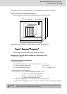
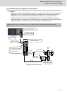
[4] To remove a detection gear fixed with shrink fitting, use the screw holes opened in the axial
direction for pulling (two M5 screw holes or two M8 screw holes), or push the end with a jig. Carry
out this work carefully. Applying excessive force when pulling out the gears could cause the inner
diameter of the detection gears to deform.
[5] Before reusing detection gears which have been removed, always measure the inner diameter
dimensions, and carefully check that the inner diameter is not deformed, and that the sufficient
tightening amount can be secured. Do not reuse the detection gears if the inner diameter is
deformed, or if any abnormality such as damage to the teeth is found.
Inner diameter
(mm)
Shrink fitting (mm)
Inner diameter
(mm)
Shrink fitting (mm)
φ40 0.020 to 0.040 φ140 0.050 to 0.085
φ70 0.030 to 0.055 φ160 0.060 to 0.090
φ80 0.030 to 0.055 φ215 0.080 to 0.110
φ125 0.050 to 0.085
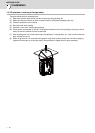
Detection
gears
Sensor section
Output connector
Thermal sensor
terminals
Thermal sensor terminals are not used
when the detector is installed on the spindle side.