MDS-D-SVJ3/SPJ3 Series Instruction Manual
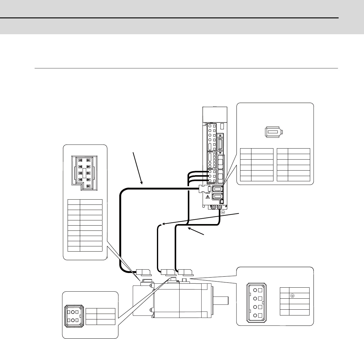
2-5 Motor and detector connection
2 - 21
2-5 Motor and detector connection
2-5-1 Connection of the servomotor
(1) Connecting the HF-KP13(B) / HF-KP23(B) / HF-KP43(B) / HF-KP73(B)
U
V
W
1
2
3
4
B1
B2
1
2
1
RQ
2
RQ*
3
CNT
4
BT
5
LG(GND)
6
SD
7
SD*
8
9
SHD
U
V
W
P5 (+5V)
LG
RQ*
SD*
2
4
6
8
10
P5 (+5V)
RQ
SD
BT
1
3
5
7
9
CN2
1 2 3 4
2
1
12
34
56
78
9
JN4AT02PJ1-R
JN4AT04NJ1-R
MDS-D-SVJ3
Power connector
Pin No.
Detector connector CN2
NamePin
Ground
Optional cable: CNV2E
(Refer to Appendix 2 for details on the
cable treatment.)
Max : 10m
No.2 No.10
No.1 No.9
Brake connector
These are 24VDC,
and have no polarity.
Detector connector
NamePin
NamePin
NamePin
NamePin
Optional cable: MR-PWS1CBL
Wiring for the motor magnetic brake
(Refer to section "2-7-3 Wiring of the
motor magnetic brake" for details.)


