


6 - 5
MDS-D-SVJ3/SPJ3 Series Instruction Manual
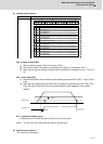
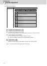
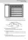
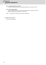
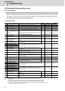
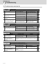
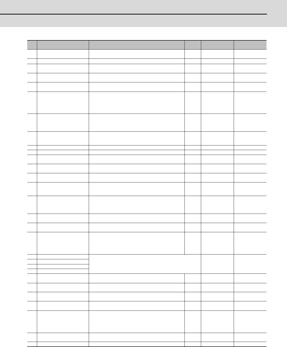
6-2 Protective functions list of units
(Note1) Definitions of terms in the table are as follows.
Main side detector: Detector connected to CN2 Sub side detector: Detector connected to CN3
(Note2) Resetting methods
NR: Reset with the NC RESET button. This alarm can also be reset with the PR and AR resetting conditions.
PR: Reset by turning the NC power ON again. This alarm can also be reset with the AR resetting conditions.
When the control axis is removed, this alarm can be reset with the NC RESET button. (Excluding alarms 32 and 37.)
AR: Reset by turning the servo drive unit power ON again.
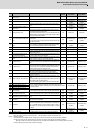
No. Name Details
Reset
method
Servo
stop method
Spindle
stop method
32
Power module error
(overcurrent)
The power module detected the overcurrent. PR Dynamic stop Coast to a stop
33
Overvoltage The bus voltage in main circuit exceeded the allowable value. PR Dynamic stop Coast to a stop
34
NC communication: CRC error The data received from the NC was outside the setting range. PR
Deceleration stop
enabled
Deceleration stop
enabled
35 NC command error
The travel command data received from the NC was exces-
sive.
PR
Deceleration stop
enabled
Deceleration stop
enabled
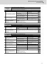
36
NC communication: Communi-
cation error
The communication with the NC was interrupted. PR
Deceleration stop
enabled
Deceleration stop
enabled
37 Initial parameter error
An incorrect set value was detected among the parameters
send from the NC at the power ON.
In the safety observation function, an error was detected in the
relation between the safety speed and safety rotation number
in the speed observation mode.
PR Initial error Initial error
38
NC communication: Protocol er-
ror 1
An error was detected in the communication frames received
from the NC.
Or, removing an axis or changing an axis was performed in the
synchronous control.
PR
Deceleration stop
enabled
Deceleration stop
enabled
39
NC communication: Protocol er-
ror 2
An error was detected in the axis data received from the NC.
Or, in changing an axis, the parameter setting of the synchro-
nous control was applied when the axis was installed.
PR
Deceleration stop
enabled
Deceleration stop
enabled
3A Overcurrent Excessive motor drive current was detected. PR Dynamic stop Coast to a stop
3B Power module error (overheat) The power module detected an overheat. PR Dynamic stop Coast to a stop
3C Regeneration circuit error
An error was detected in the regenerative transistor or in the
regenerative resistor.
PR Dynamic stop -
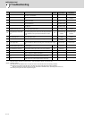
3D
Power supply voltage error at
acceleration/deceleration
A motor control error during acceleration/deceleration, due to
a power voltage failure, was detected.
PR Dynamic stop -
3E
Magnetic pole position detection
error
The magnetic pole position, detected in the magnetic pole po-
sition detection control, is not correctly detected.
AR Dynamic stop Coast to a stop
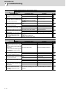
41 Feedback error 3
Either a missed feedback pulse in the motor side detector or
an error in the Z-phase was detected in the full closed loop sys-
tem.
PR Dynamic stop Coast to a stop
42 Feedback error 1
Either a missed feedback pulse in the position detection or an
error in the Z-phase was detected. Or the distance-coded ref-
erence check error exceeded the allowable value when the
distance-coded reference scale was used.
PR Dynamic stop Coast to a stop
43 Feedback error 2
An excessive difference in feedback was detected between
the machine side detector and the motor side detector.
PR Dynamic stop Coast to a stop
45 Fan stop
An overheat of the power module was detected during the
cooling fan stopping.
PR Dynamic stop Coast to a stop
46 Motor overheat / Thermal error
Either the motor or the motor side detector detected an over-
heat.
Or, the thermistor signal receiving circuit of the linear motor or
direct-drive motor was disconnected.
Or, the thermistor signal receiving circuit was short-circuited.
NR
Deceleration stop
enabled
Deceleration stop
enabled
48 Main side detector: Error 5
An error was detected by the detector connected to the main side.
The error details are different according to the connected detector. Refer
to "Detector alarm".
Dynamic stop Coast to a stop
49 Main side detector: Error 6
4A Main side detector: Error 7
4B Main side detector: Error 8
4C
C
urrent error at initial magnetic
pole estimate
Current detection failed at the initial magnetic pole estimation. NR Dynamic stop Coast to a stop
4E NC command mode error An error was detected in the control mode send from the NC. NR
Deceleration stop
enabled
Deceleration stop
enabled
4F Instantaneous power interrupt
The control power supply has been shut down for 50ms or
more.
NR
Deceleration stop
enabled
Deceleration stop
enabled
50 Overload 1
Overload detection level became 100% or more. The motor or
the drive unit is overloaded.
NR
Deceleration stop
enabled
Deceleration stop
enabled
51 Overload 2
In a servo system, current command of 95% or more of the
unit’s max. current was given continuously for 1 second or lon-
ger. In a spindle system, current command of 95% or more of
the motor’s max. current was given continuously for 1 second
or longer.
NR
Deceleration stop
enabled
Deceleration stop
enabled
52 Excessive error 1 A position tracking error during servo ON was excessive. NR
Deceleration stop
enabled
Deceleration stop
enabled
53 Excessive error 2 A position tracking error during servo OFF was excessive. NR Dynamic stop -