


2 Wiring and Connection
MITSUBISHI CNC
2 - 20
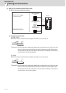
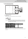
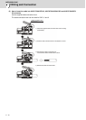
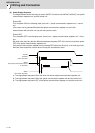
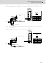
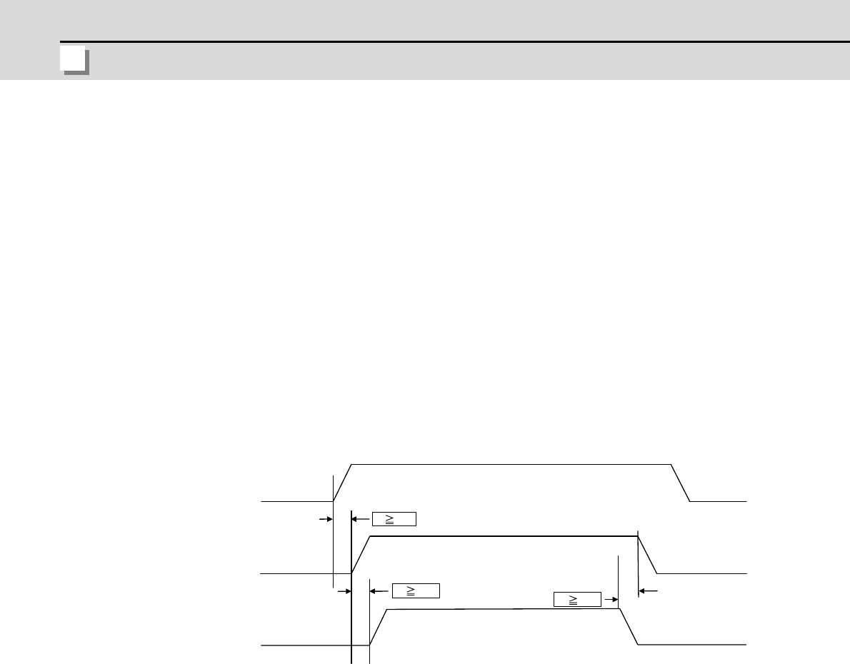
(2) Power Supply Sequence
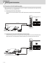
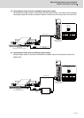
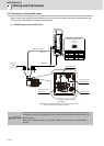
The diagram below shows the timing of power ON/OFF of the drive unit 200VAC (400VAC), the optical
communication repeater unit, and the control unit.
[Power ON]
Turn the power ON in the following order; drive unit -> optical communication repeater unit -> control
unit
If the control unit is powered ON before the optical communication repeater unit, the initial
communication with the drive unit may fail and cause an alarm.
[Power OFF]
Turn the power OFF in the following order; control unit -> optical communication repeater unit -> drive
unit.
Set aside more than 8ms the time difference between the power OFF of the control unit and the power
OFF of the optical communication repeater unit.
If the optical communication repeater unit is powered OFF before the drive unit, or the time lag is less
than 8ms, data acquisition from the drive unit may fail and cause an alarm.
t1: Time lag between the power-ON of the drive unit and the optical communication repeater unit
t2: Time lag between the power-ON of the optical communication repeater unit and the control unit
t3: Time lag between the power-OFF of the optical communication repeater unit and the control unit
200VAC
(400VAC)
(Drive unit power)
24VDC
(The optical communication repeat-
er unit power)
24VDC
(The control unit power)