


6 - 12
6 Troubleshooting
MITSUBISHI CNC
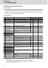
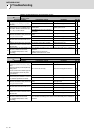
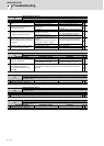
Alarm No.
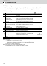
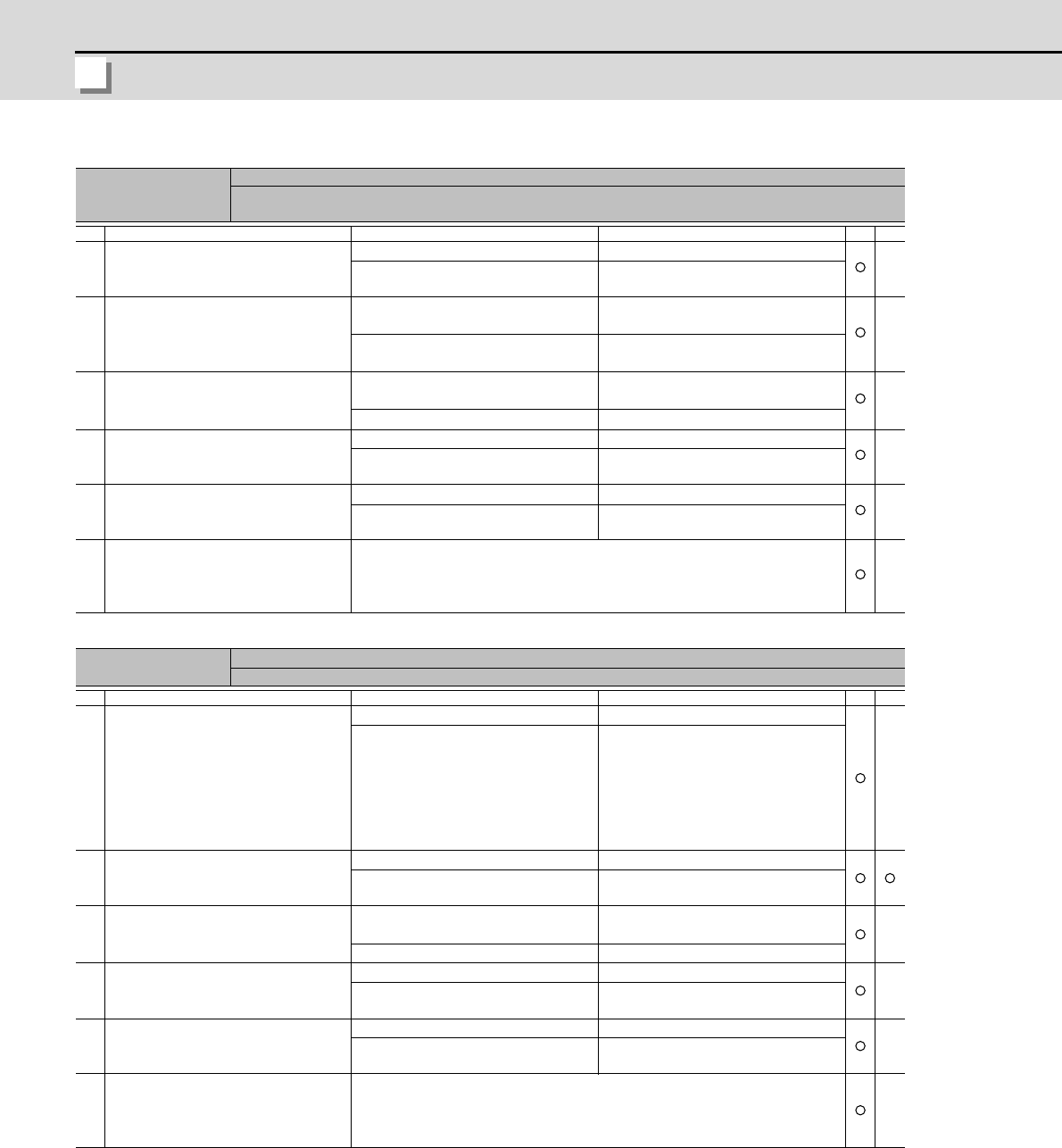
19
Detector communication error in synchronous control:
An error was detected in the machine side detector of the secondary axis at the speed command synchro-
nization control.
Investigation details Investigation results Remedies SV SP
1
Check the servo parameter value of
secondary axis (SV025.pen:position
detector).
The value is not set correctly. Correctly set.
The value is set correctly. Check the investigation item No. 2.
2
Check if there are no problems in the
connection between the detector (lin-
ear scale) and MDS-B-HR.
The screw connected to MDS-B-HR is
winded down.
Tighten up the screw.
No problems found in the connector
connection.
Check the investigation item No. 3.
3
Jiggle the detector connectors (drive
unit side and detector side) and check
if they are disconnected.
The connector is disconnected (or
loose).
Correctly install.
The connector is not disconnected. Check the investigation item No. 3.
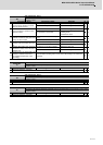
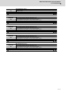
4
Turn the power OFF, and check the
detector cable connection with a tes-
ter.
The connection is faulty. Replace the detector cable.
The connection is normal. Check the investigation item No. 4.
5
Replace with another unit, and check
whether the fault is on the unit side or
detector side.
The alarm is on the drive unit side. Replace the drive unit.
The alarm is on the detector side. Check the investigation item No. 5.
6
Check if there is any abnormality in the
detector's ambient environment.
(Ex. Ambient temperature, noise,
grounding)
Take remedies according to the causes of the abnormality in the ambient en-
vironment.
[1] Machine grounding check
[2] Shield connection of the cable
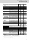
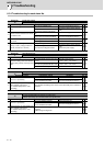
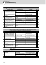
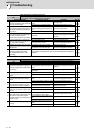
Alarm No.
1A
Sub side detector: Initial communication error
Initial communication with the machine side detector failed.
Investigation details Investigation results Remedies SV SP
1
Check the servo parameter
(SV025.pen:position detector) setting
value.
Check the spindle parameter(SP019)
setting value.
Are the serial communication type de-
tector parameters set for the pulse
type detector?
The value is not set correctly. Correctly set SV025.
The value is set correctly. Check the investigation item No. 2.
2
Check the detector.
Check if the pulse detector is used for
the detector specified to be serial.
The pulse detector is used. Replace the detector.
The serial detector is used. Check the investigation item No. 3.
3
Jiggle the detector connectors (drive
unit side and detector side) and check
if they are disconnected.
The connector is disconnected (or
loose).
Correctly install.
The connector is not disconnected. Check the investigation item No. 4.
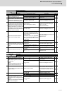
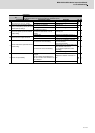
4
Turn the power OFF, and check the
detector cable connection with a tes-
ter.
The connection is faulty. Replace the detector cable.
The connection is normal. Check the investigation item No. 5.
5
Replace with another unit, and check
whether the fault is on the unit side or
detector side.
The alarm is on the drive unit side. Replace the drive unit.
The alarm is on the detector side. Check the investigation item No. 6.
6
Check if there is any abnormality in the
detector's ambient environment.
(Ex. Ambient temperature, noise,
grounding)
Take remedies according to the causes of the abnormality in the ambient en-
vironment.