


2 Wiring and Connection
MITSUBISHI CNC
2 - 38
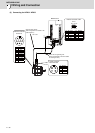
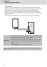
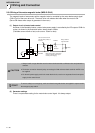
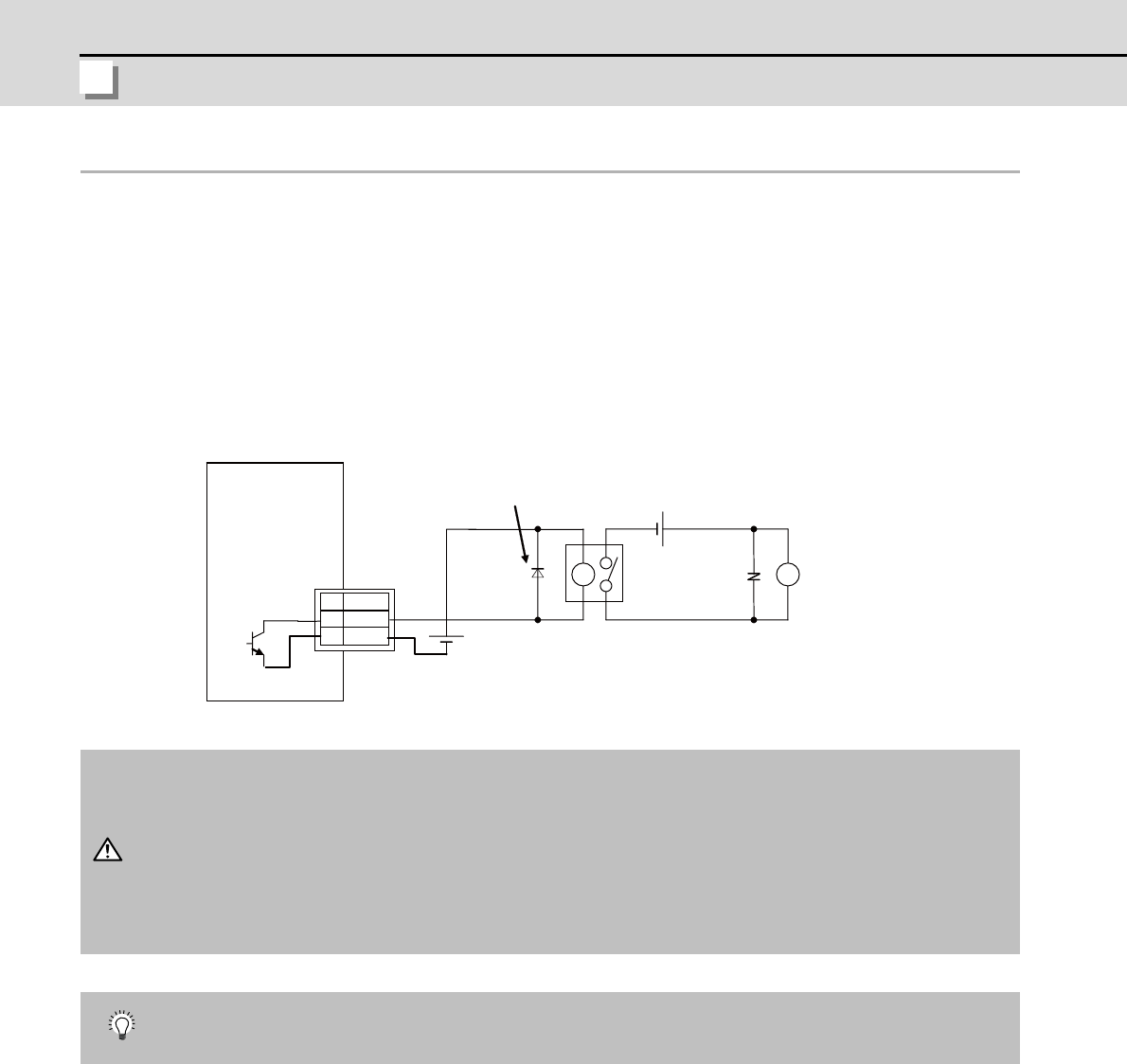
2-8-3 Wiring of the motor magnetic brake (MDS-D-SVJ3)
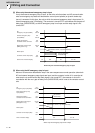
The magnetic brake of servomotors with a magnetic brake is controlled by the motor brake control signal
(CN9-13 pin) of the servo drive unit. The servo drive unit releases the brake when the motor is ON.
(Servo ON means when torque is generated in the motor.)
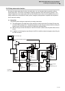
(1) Output circuit of motor brake control
As shown in the illustration below, a motor brake power supply is controlled by the DO output of CN9 via
a relay. As shown in the illustration below, always install a diode.
(Tolerable current: 40mA or less, rush current: 100mA or less)
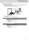
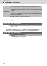
(2) Parameter settings
There is no parameter setting for the motor brake control signal. It is always output.
1. Always install a surge absorber near the motor's brake terminal to eliminate noise and protect the
contacts.
2. The brakes cannot be released just by connecting the CN9 and motor brake terminal. 24VDC must
be supplied.
3. For the 24V power supply used in the motor brake circuit, use the one separated from the 24 power
supply for the control circuit.
To ensure safety in an emergency, make sure that the magnetic brakes are applied in sequence with
the emergency stop switch.
5
13
3
MDS-D-SVJ3
CN9
DICOM
MBR
DOCOM
24VDC
24VDC
The servo drive unit will
fail if the diode polarity is
incorrect.
Always install a
surge absorber.
Brake
Brake control relay (The brakes
cannot be directly driven by an
internal power supply.)
Surge
absorber
CAUTION
POINT