


5 - 10
5 Spindle Adjustment
MITSUBISHI CNC
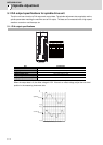
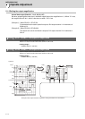
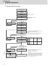
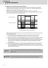
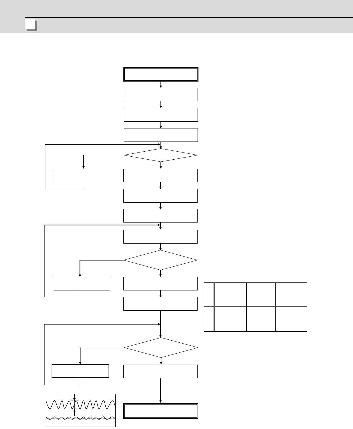
(3) Adjusting the speed loop parameter
Stops at servo ON status
Increase the value up to where
resonance occurs.
Set SP005 (standard setting 150)
Command M19 (orientation stop)
Adjust speed loop gain
Set SP001=15
Resonance occurs?
Increase SP005 by +20
Emergency stop
Command M19 (orientation stop)
Increase SP005 by -20
Subtract 20 from SP005
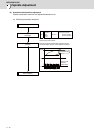
Acceleration/deceleration
operation
Resonance
(abnormal noise) or abnormal
operation occurs?
Command M19 (orientation stop)
Set D/A output as shown
on the right.
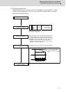
Waveform
for Ref.
0.045
°
or less
q
axis current command
Position droo
p
Adjustment completed
Multiply SP005 by 0.9
Subtract 3 from SP005
Is droop oscillation
0.045°p-p or less?
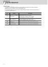
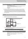
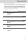
Note that the maximum setting value is as follows:
SP005(max)150 x inertia ratio
(Inertia ratio total inertia/motor inertia
(Example)
When inertia rate is double and the determined gain is
350, the setting value for SP005 is 315, which is 90%
of the determined gain, however,the setting value for
SP005 should be 300, because the maximum setting
value is 150x2(inertia rate)=300.
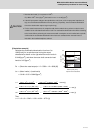
Output
waveform
Position
droop
Output
waveform
q axis current
command
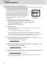
Executes acceleration/deceleration operation in phase
up to maximum rotation speed from 0.
(Note)
hen the maximum speed is 10000r/min, executes in
approx. 1000r/min increments, divided by 10.
SP125 60
SP126 2
SP127 4000
(0.025°/V)
SP128:1000
(10%/V)
Ch1
Ch2
Yes
NO
YES
NO
0
0
NO
YES