


6 - 21
MDS-D-SVJ3/SPJ3 Series Instruction Manual
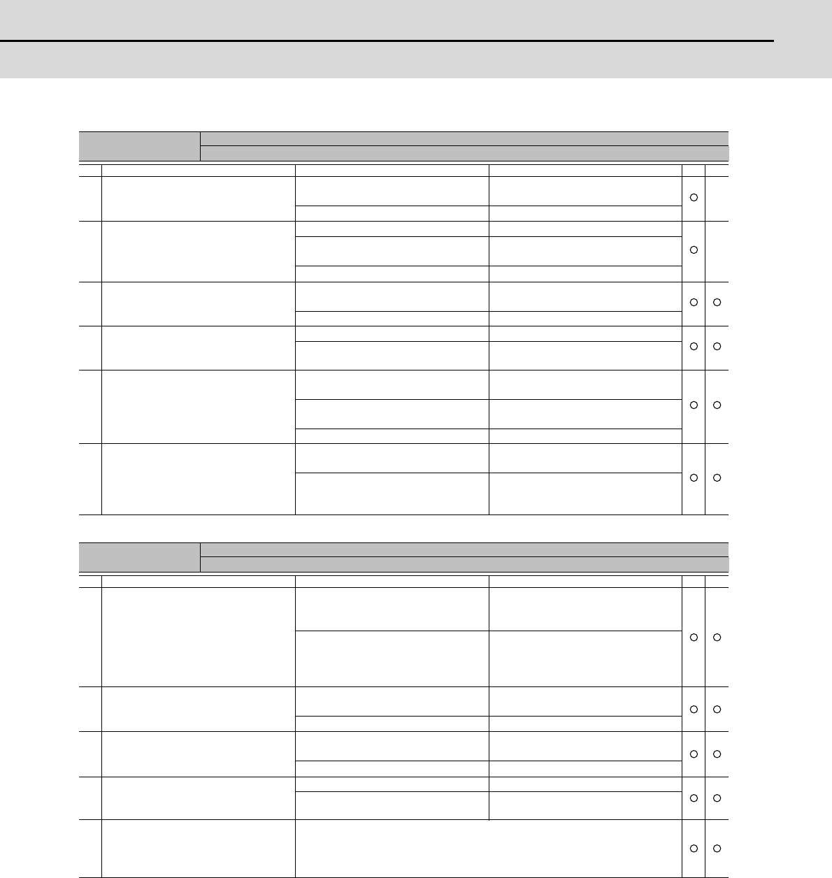
6-3 Troubleshooting
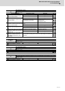
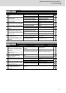
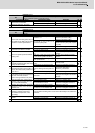
Alarm No.
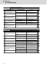
33
Overvoltage:
The main circuit bus voltage exceeded the tolerable value.
Investigation details Investigation results Remedies SV SP
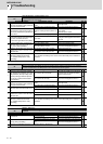
1
Is an external regenerative resistor
used?
An external regenerative resistor is
used.
Check the investigation item No. 3.
A built-in regenerative resistor is used. Check the investigation item No. 2.
2
Is the short wire connected between P
and D terminal?
Are there any problems with the con-
nection condition?
The wire is not connected. Connect the wire.
The connector is disconnected.
The connector has a contact fault.
Reconnect the connector.
Replace the connector.
The connection is correct. Check the investigation item No.6.
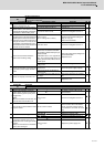
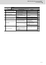
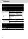
3
Is the combination of the used regen-
erative resistor and drive unit appropri-
ate?
The combination is incorrect.
Replace the correct regenerative re-
sistor.
The combination is normal. Check the investigation item No. 4.
4
Is the connection of the regenerative
resistor or regeneration resistor cable
correct?
The connection is incorrect. Rewire.
The connection is correct. Check the investigation item No. 5.
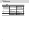
5
Is the regeneration resistor or the re-
generation resistor cable broken?
Disconnect the regenerative resistor
terminal and check the resistance val-
ue with a tester.
The regeneration resistor is broken.
Or the resistance value is large.
Replace the regenerative resistor.
The regeneration resistor cable is bro-
ken.
Replace the cable.
The resistance value is normal. Check the investigation item No. 6.
6
The acceleration/deceleration time
constant is too short.
At acceleration/deceleration, has the
speed overshoot reached to the cur-
rent limit?
Reached to the current limit.
The speed overshoot is applied.
Increase the acceleration/deceleration
time constant.
The connection is normal. Replace the drive unit.
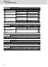
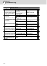
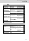
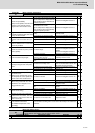
Alarm No.
34
NC-DRV communication: CRC error
An error was detected in the data received from the CNC.
Investigation details Investigation results Remedies SV SP
1
Gently shake the connectors of the op-
tical cables by hand that link between
NC and drive unit or between drive
units to check for loosening and dis-
connection.
Also check if an excessive force is not
applied on them.
The connector is loose or nearly dis-
connected. The tab of the connector is
damaged.
Correctly install.
Replace the cable.
The connector is not disconnected. Check the investigation item No. 2.
2
Check for damages at the ends of the
optical communication cable.
Replace the cable.
The damage is found at the end of the
cable.
Replace the communication cable.
The connection is normal. Check the investigation item No. 3.
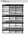
3
Check whether the NC or drive unit
software version was changed recent-
ly.
The version was changed.
Change software version back to the
original.
The version was not changed. Check the investigation item No. 4.
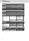
4
Replace with another drive unit, and
check whether the fault is on the NC
side or drive unit side.
The alarm is on the drive unit side. Replace the drive unit.
The alarm is on the unit connections. Check the investigation item No. 5.
5
Check if there is any abnormality in the
unit's ambient environment.
(Ex. Ambient temperature, noise,
grounding)
Take remedies according to the causes of the abnormality in the ambient en-
vironment.