


6 - 24
6 Troubleshooting
MITSUBISHI CNC
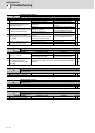
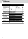
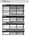
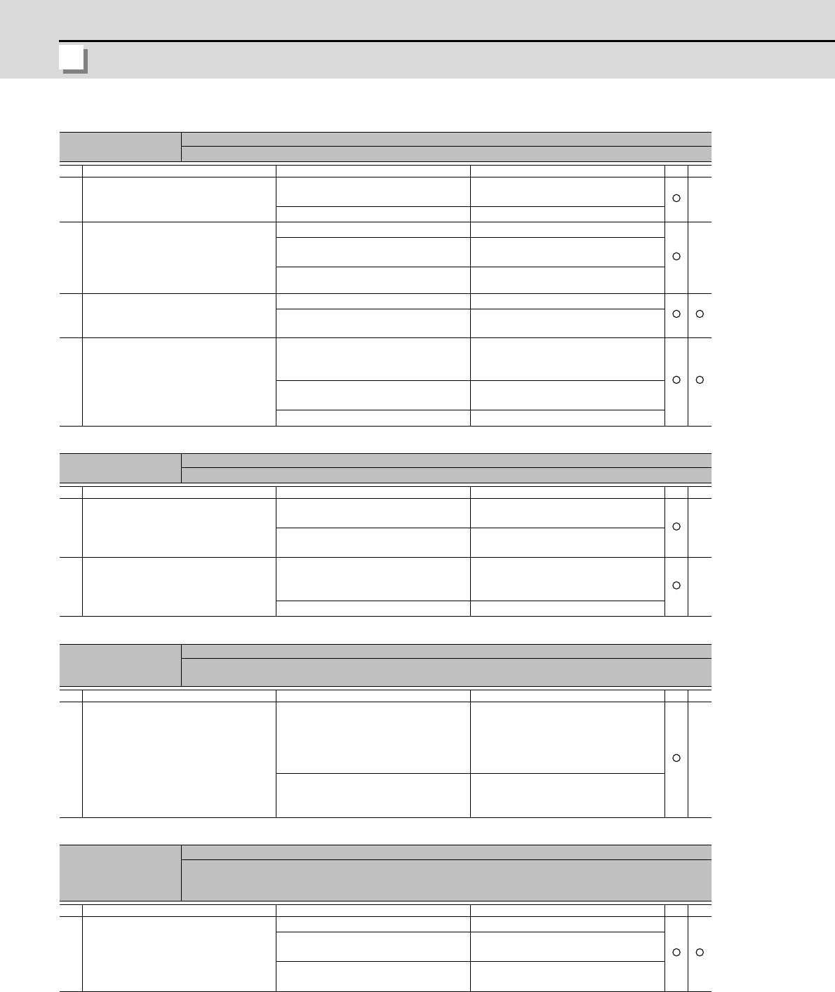
Alarm No.
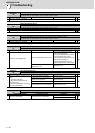
3C
Regeneration circuit error:
An error was detected in the regenerative transistor or in the regenerative resistor.
Investigation details Investigation results Remedies SV SP
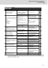
1
Check if an external regenerative re-
sistor is used.
An external regenerative resistor is
used.
Check the investigation item No. 3.
A built-in regenerative resistor is used. Check the investigation item No. 2.
2
Is the short wire connected between P
and D terminal?
Are there any problems with the con-
nection condition? (looseness of the
screw)
The wire is not connected. Connect the wire.
The connector is disconnected.
The connector has a contact fault.
Reconnect the connector.
Replace the connector.
The connection is correct. Replace the drive unit.
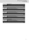
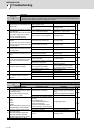
3
Is the connection of the regenerative
resistor or regeneration resistor cable
correct?
The wire is not connected. Connect the wire.
The connection is correct. Check the investigation item No. 4.
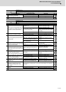
4
Is the regeneration resistor or the re-
generation resistor cable broken?
Disconnect the regenerative resistor
terminal and check the resistance val-
ue with a tester.
The regeneration resistor is broken.
Or the resistance value is different
from the specified value.
Replace the regenerative resistor.
The regeneration resistor cable is bro-
ken.
Replace the cable.
The resistance value is normal. Replace the drive unit.
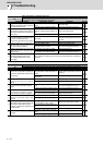
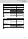
Alarm No.
3D
Power supply voltage error at acceleration/deceleration:
A motor control error was detected at acceleration/deceleration due to an input voltage drop.
Investigation details Investigation results Remedies SV SP
1
Measure the input voltage during op-
erations with a tester.
During operations, the voltage fluctu-
ates widely.
Increase the power capacity (KVA).
-
During operations, the voltage is sta-
ble.
Check the investigation item No. 2.
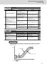
2 Check the load inertia.
The load inertia (workpiece etc.) is ex-
cessive.
[1] Lower the load inertia.
[2] Extend the rapid traverse time con-
stant for G0/G1.
-
The load inertia is normal. Replace the drive unit.
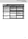
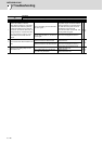
Alarm No.
3E
Magnetic pole position detection error:
The magnetic pole position is not reliable in the magnetic pole position detection control.
This alarm occurs at the detection level which is set in SV094.
Investigation details Investigation results Remedies SV SP
1
Adjust the setting value of the servo
parameter SV094 and detect the mag-
netic pole position.
Set SV094.
Set SV094.
The standard value for a rotary motor
is 100.
The standard value for a linear motor
is 10.
-
SV094 is set.
Set the optimal value allowing for the
coasting distance (Increase the val-
ue).
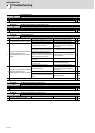
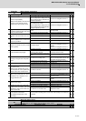
Alarm No.
41
Feedback error 3
Either a missed feedback pulse in the main side incremental detector or an error in the Z-phase was detect-
ed in the full closed loop system. In the servo, Z-phase was not detected by a rotary detector within 2 rota-
tions.
Investigation details Investigation results Remedies SV SP
1
Check the connection condition of the
cable and detector.
- Check if the cable is disconnected.
The cable is disconnected. Replace the cable.
The cable is normal.
Check for dirt on the connector termi-
nal and reconnect it.
The alarm occurs even after it is re-
connected.
Replace the detector.