


Appendix 3 Precautions in Installing Spindle Motor
MITSUBISHI CNC
Appendix 3 - 6
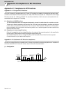
Appendix 3-7 Example of unbalance correction
Unbalance correction is normally performed by rotating a rotor at a constant speed. The unbalance on the
rotor appears in the form of vibration that has a frequency of one cycle per revolution.
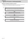
<How to balance>
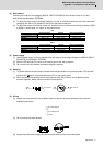
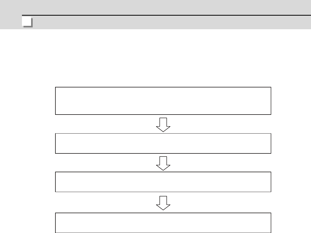
Step 1
Step 2
Step 3
Step 4
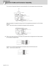
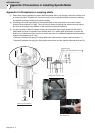
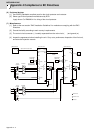
To grasp the present situation, drive the motor with the gear, pulley and coupling attached, and detect
the reflection sticker attached on the rotor using a revolution indicator (this is a rotation signal). And
also detect an acceleration signal using an acceleration pickup attached on the bracket. Then input
these signals to each balancing machine to measure the present unbalance force.
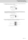
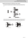
Add trial weights to the balance correction holes on the gear,
pulley and coupling and measure the unbalance in the same way.
When you input the two data in a balancing machine, the machine shows where to correct.
Then, follow the instruction to carry out balancing.
For confirmation, check the unbalance again.
* If further balancing is required, repeat from Step 2.