


6 - 11
MDS-D-SVJ3/SPJ3 Series Instruction Manual
6-3 Troubleshooting
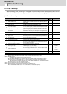
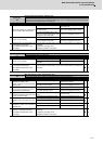
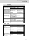
Alarm No.
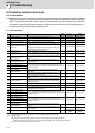
16
Initial magnetic pole position detection error
In linear motor or IPM spindle motor using absolute position detector, the servo ON has been set before the
magnetic pole shift amount(servo:SV028,spindle:SP118) is set. In the initial magnetic pole position detec-
tion control, the pole position was not correctly set.
Investigation details Investigation results Remedies SV SP
1
Check the parameters, SV028 (for the
servo) and SP118(for the spindle).
The parameters have not been set.
Set the magnetic shift pole
amount(SP118).
The parameters have been set, but
the alarm occurs.
Carry out the magnetic pole estimation
again, as the setting value is wrong.
The setting parameter value is the
same even when initial magnetic pole
function was executed again.
Check the investigation item No. 2.
2 Check the repeatability.
The error is always repeated. Replace the drive unit.
The state returns to normal once, but
occurs sometimes thereafter.
Check the investigation item No. 3.
3
Check if there is any abnormality in the
unit's ambient environment.
(Ex. Ambient temperature, noise,
grounding)
Take remedies according to the causes of the abnormality in the ambient en-
vironment.
[1] Machine grounding check
[2] Shield connection of the cable
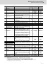
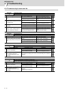
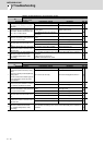
Alarm No.
17
A/D converter error
An error was detected in the current FB.
Investigation details Investigation results Remedies SV SP
1 Check the repeatability.
The error is always repeated. Replace the drive unit.
The state returns to normal, but occurs
thereafter.
Check the investigation item No. 2.
2
Check if there is any abnormality in the
unit's ambient environment.
(Ex. Ambient temperature, noise,
grounding)
Take remedies according to the causes of the abnormality in the ambient en-
vironment.
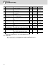
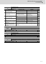
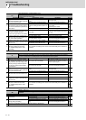
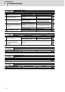
Alarm No.
18
Main side detector: Initial communication error
An error was detected in the initial communication with the motor side detector.
Investigation details Investigation results Remedies SV SP
1
Check the servo parameter
(SV025.ent) setting value.
Check the spindle parameter(SP020)
setting value.
The value is not set correctly.
Correctly set SV025 for the servo, and
SP020 for the spindle.
The value is set correctly. Check the investigation item No. 3.
2
Check the detector.
Check if a pulse detector is used for
serial detector specifications.
The pulse detector is used. Replace the detector to the serial.
The serial detector is used. Check the investigation item No. 3.
3
Jiggle the detector connectors (drive
unit side and detector side) and check
if they are disconnected.
The connector is disconnected (or
loose).
Correctly install.
The connector is not disconnected. Check the investigation item No. 4.
4
Turn the power OFF, and check the
detector cable connection with a tes-
ter.
The connection is faulty. Replace the detector cable.
The connection is normal. Check the investigation item No. 5.
5
Replace with another unit, and check
whether the fault is on the unit side or
detector side.
The alarm is on the drive unit side. Replace the drive unit.
The alarm is on the detector side. Check the investigation item No. 6.
6
Check if there is any abnormality in the
detector's ambient environment.
(Ex. Ambient temperature, noise,
grounding)
Take remedies according to the causes of the abnormality in the ambient en-
vironment.
[1] Machine grounding check
[2] Shield connection of the cable