MDS-D-SVJ3/SPJ3 Series Instruction Manual
2-5 Motor and detector connection
2 - 27
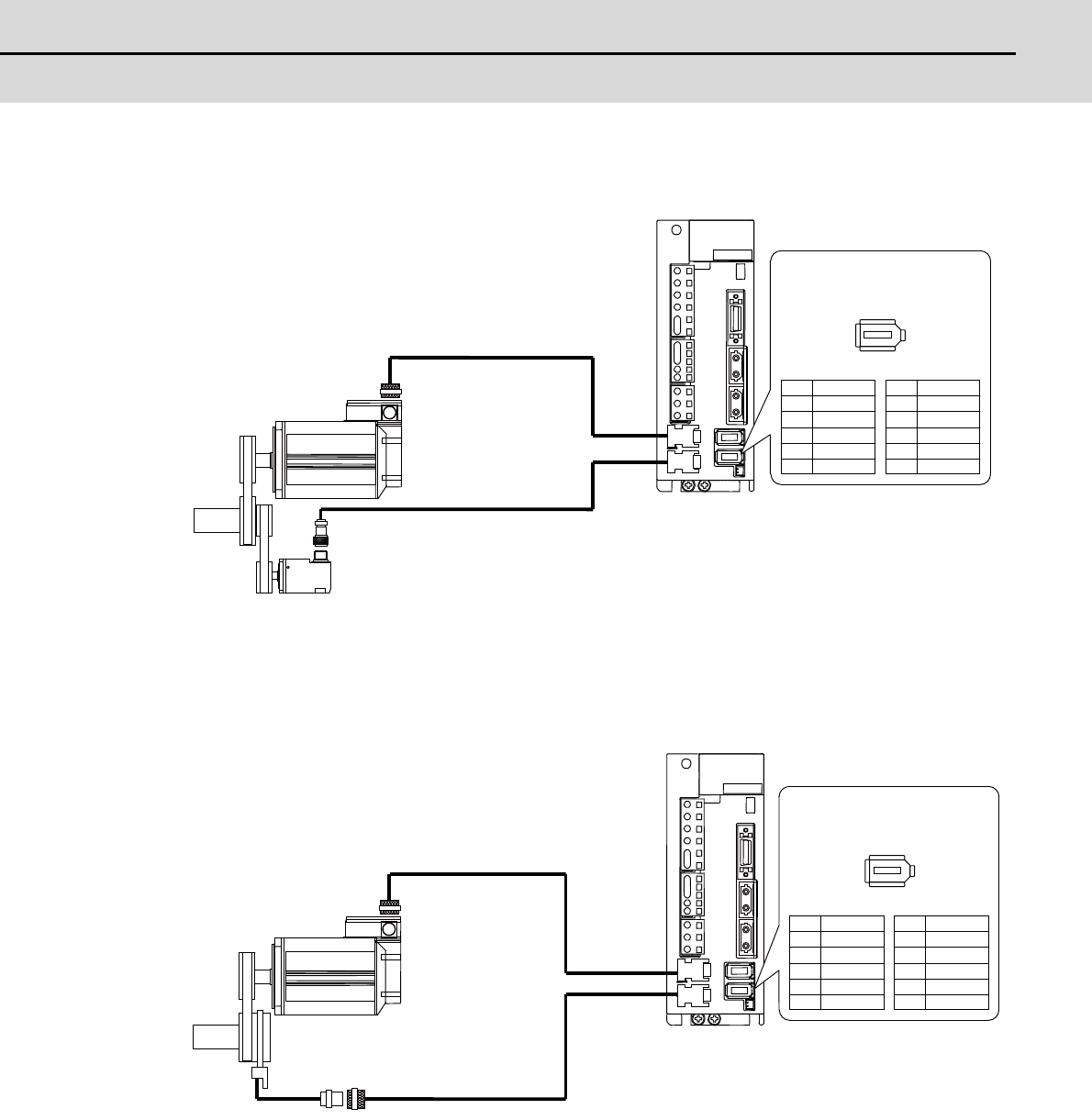
(2) Connecting the spindle side ABZ pulse output detector (OSE-1024-3-15-68, OSE-1024-3-15-68-8)
(Note) Confirm that the gear ratio (pulley ratio) of the spindle end to the detector is 1:1. Use a timing belt
for connecting.
(3) Connecting the spindle side PLG serial output detector (TS5690 Series)
CN2
CN3
MDS-D-SPJ3
1
3
5
7
9
P5(+5V)
A
Z
B
2
4
6
8
10
LG
A*
B*
Z*
ABZSEL*
Name
Name
Pin Pin
No.1 No.9
No.2 No.10
Pin No.
Detector connector CN3
Spindle side detector
Spindle
Spindle motor
CNP2E-1 cable
max.30m
CNP3EZ cable
max.30m
CN2
CN3
MDS-D-SPJ3
1
3
5
7
9
P5(+5V)
RQ
SD
2
4
6
8
10
LG
RQ*
SD*
No.1 No.9
No.2 No.10
Pin No.
Detector connector CN3
Name
Name
Pin Pin
Spindle
Spindle motor
CNP2E-1 cable
max.30m
Spindle side accuracy detector
TS5690 series
CNP2E-1 cable
max.30m


