


Appendix 3 Precautions in Installing Spindle Motor
MITSUBISHI CNC
Appendix 3 - 4
Appendix 3-4 Precautions in coupling shafts
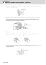
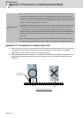
(1) When direct coupling between the motor shaft and spindle shaft is not accurate, abnormal vibration and/
or sound may result. Therefore, do not rely too much on the coupling's flexibility but perform centering
and parallel correcting carefully during shaft coupling.
(2) According to the motor specifications, the allowable load on the motor shaft in the motor's inward
direction (thrust direction) is 0 [kgf]. Thus you have to choose a coupling that causes no thrust load on
the motor shaft, and also pay attention to the extension by thermal expansion.
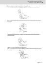
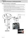
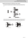
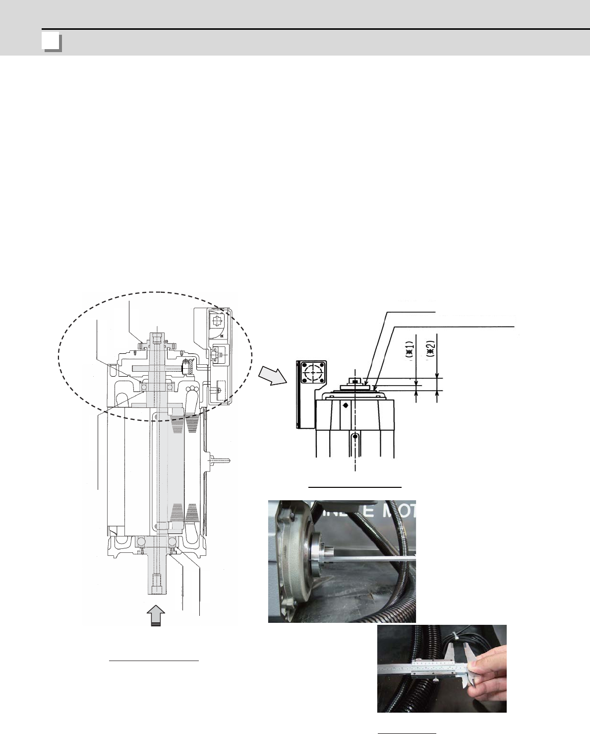
(3) If a gear coupling or Oldham coupling is used, the motor shaft may be kept pushed into the motor's
inward when the shaft is inserted into the spindle head. For a hollow-shaft specification, measure the
distance A or B before and after insertion to confirm that there is no difference between before and after
insertion (the allowance is ±0.1mm)
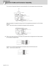
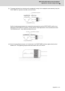
- Distance A: between the rotary joint fitting attachment surface and the rotation seal's end face (*1)
- Distance B: between the rotary joint fitting attachment surface and the opposite load side shaft end (*2)
B
A
Rotation seal
Bearing
pre-load spring
Opposite load side Bearing
Load side Bearing
Rotation seal
Rotation seal
Rotary joint fitting attachment surface
Enlarged view of motor rear
Motor structural drawing
Thrust load
How to measure