


4 - 61
MDS-D-SVJ3/SPJ3 Series Instruction Manual
4-8 Servo control signal
4-8-2 Servo control output (Servo to NC)
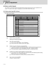
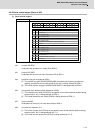
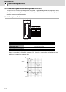
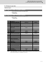
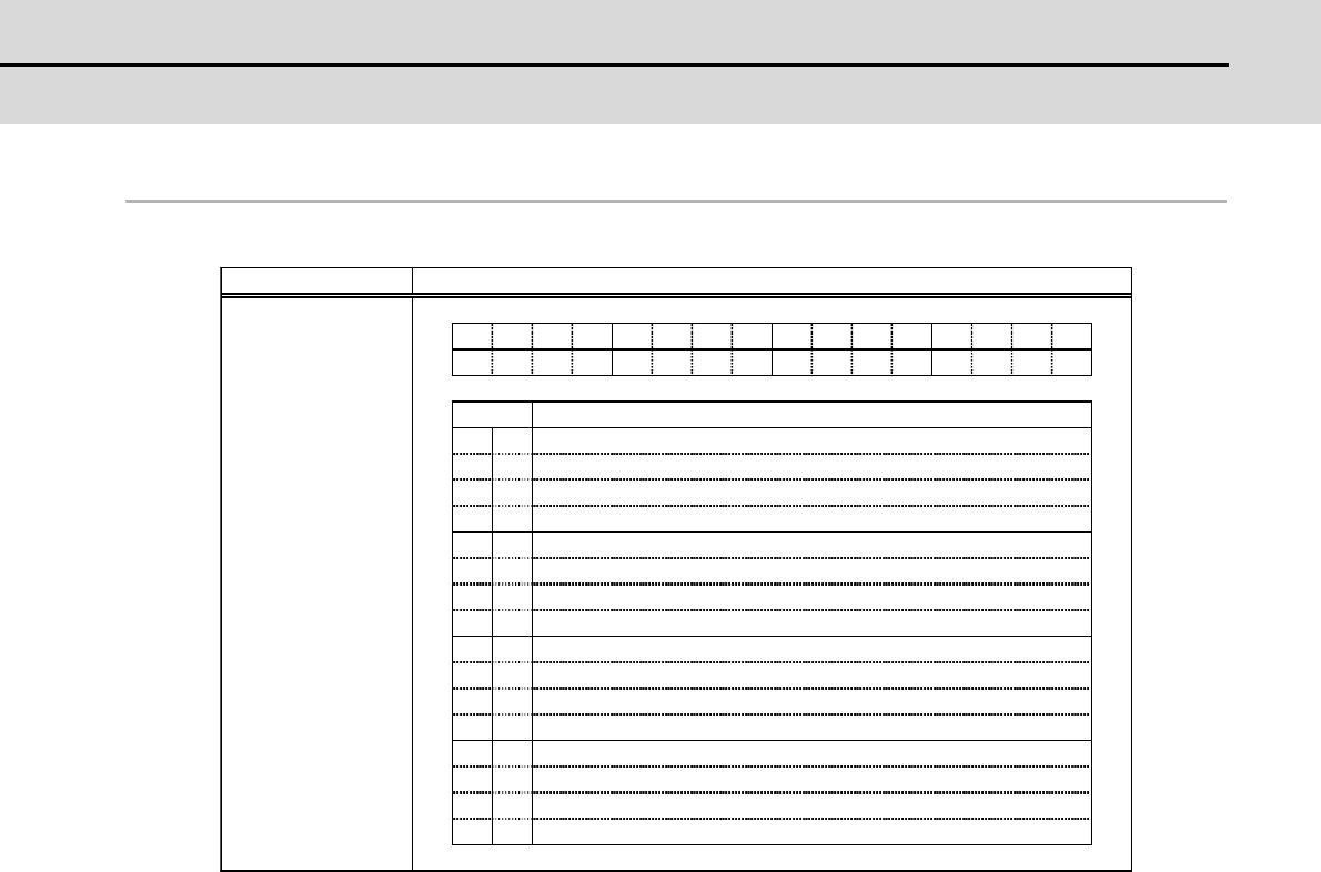
(1) Servo control output 1
bit0. In ready ON (RDY)
It indicates that the status is in ready ON at RDN=1.
bit1. In servo ON (SRV)
It indicates that the drive unit turns ON (servo ON) at SRV=1.
bit4. In position loop gain changeover (KPM)
[1] The position loop gain (SV049/SV050/SV058) for spindle synchronous (synchronous
tapping, synchronous control with spindle C-axis, etc.) is being selected at KPM=1.
[2] The normal position loop gain (SV003/SV004/SV057) is being selected at KPM=0.
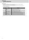
bit6. In excessive error detection width changeover (EOM)
[1] The excessive error width (SV053) for the special control (initial absolute position setting,
stopper control, etc.) is being selected at EOM =1.
[2] The normal excessive error width (SV023) is being selected at EOM =0.
bit7. In alarm (ALMR)
It indicates that drive unit is in some alarm state at ALM=1.
bit8. In current limit selection (IL1)
[1] The current (torque) limit (SV014) for the special control (initial absolute position setting,
stopper control, etc.) is being selected at IL1 =1.
[2] The normal current (torque) limit (SV013) is being selected at IL1 =0.
FEDCBA9876543210
bit
0
1
2
3
4
5
6
7
8
9
A
B
C
D
E
F
RDY
SRV
-
-
KPM
-
EOM
IL1
-
-
-
RDYSRV
KPMEOM
ALMR
IL1
INPLMTAER
WRN
INP
LMT
AER
WRN
ALMR
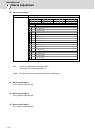
Details
Name Details
Servo control output 1
In READY ON
In servo ON
(For maintenance)
In position loop gain changeover
In excessive error detection width changeover
In alarm
In current limit selection
(For maintenance)
(For maintenance)
(For maintenance)
(For maintenance)
(For maintenance)
In in-position
In current limit
In warning
In absolute position data loss