


5 - 28
5 Spindle Adjustment
MITSUBISHI CNC
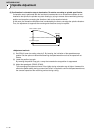
(3) Setting the notch filter
During spindle C axis operation, there are times where motor is rotated while brake is applied, resulting
in resonance occurred. In this case, measure resonance frequency from q axis current command
waveform and set the value to SP038 (notch filter 1). Also, depending on the set frequency, filter depth
must be set to SP034. When notch filter is set, perform acceleration/deceleration operation at the
maximum speed and confirm that no abnormal oscillation or noise is found.
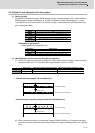
Notch filter's set frequency and standard depth setting
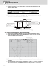
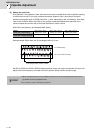
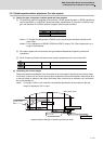
Setting example: When there are 16 wavelengths within 0.02 sec.
Set 800 to SP038 and XXX0 to SP034. Measure position droop and current command at this time, and
adjust notch filter's frequency and depth so that the position droop is within standard range.
SP034
Notch filter 1 Depth setting
bit3=0 bit2=0 bit1=0
Setting value: XXX0
bit3=0 bit2=1 bit1=0
Setting value: XXX4
bit3=1 bit2=0 bit1=0
Setting value: XXX8
SP038
Notch filter 1 Setting frequency
2000(Hz) to 400(Hz) 399(Hz) to 200(Hz) 190(Hz) or lower
1. When incorrect frequency is set, suddenly resonance can occur and big abnormal noise can be
generated. Input the appropriate value.
2. Do not set the value to low-frequency (50Hz).
Ch1: Position
droop
Ch2: q axis current command
0
0
16 wavelengths within 0.02sec = 800Hz
POINT