MDS-D-SVJ3/SPJ3 Series Instruction Manual
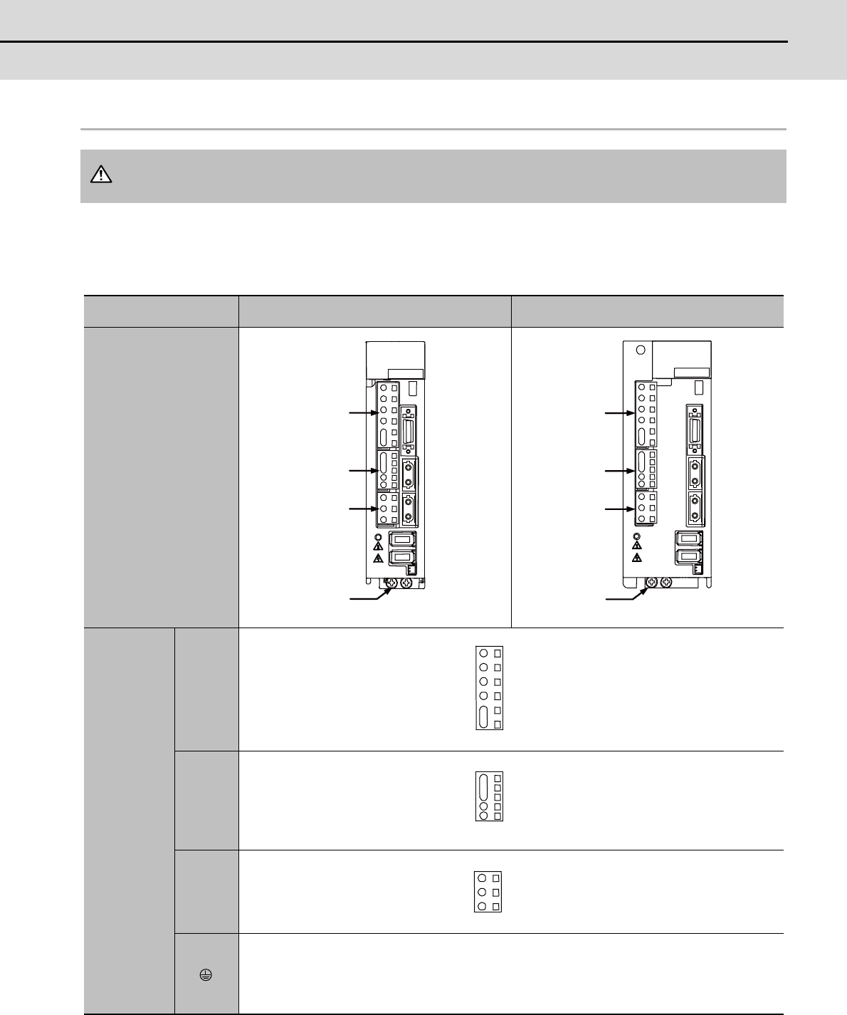
2-2 Main circuit terminal block/control circuit connector
2 - 5
2-2-2 Connector pin assignment
(1) Main circuit terminal block and connector
Power supply unit
(Note) The illustrations of drive units are shown as an example.
Do not apply a voltage other than that specified in Instruction Manual on each terminal. Failure to
observe this item could lead to rupture or damage, etc.
Unit
Terminal
MDS-D-SVJ3-03NA to 04NA
MDS-D-SVJ3-07NA
MDS-D-SPJ3-075NA
Terminal
position
Terminal
specification/
Pin
assignment
[1] CNP1
[2] CNP2
[3] CNP3
[4]
Screw size: M4 x 10
Tightening torque: 1.2Nm
CAUTION
[1]
[2]
[3]
[4]
[1]
[2]
[3]
[4]
L1
L2
L3
N
P1
P2
P
C
D
L11
L21
U
V
W


