


198
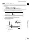
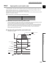
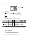
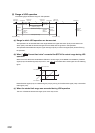
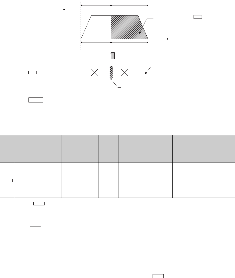
(a) Operation of a speed-position movement amount change
The operation is as follows.
(b) New speed-position movement amount
The setting is cleared to 0 when the next operation starts.
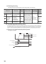
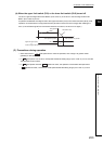
(c) Data setting
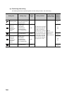
The following table lists the data to be set, setting condition, and check timing.
If " New speed-position movement amount" is a value that moves the workpiece outside the stroke limit
range, the error "Movement outside the stroke limit range" (error code: 87) occurs at the input of Speed-
position switching command signal (CHANGE), and the set new movement amount is ignored. (The value in
" Positioning address P1" (movement amount) is used.)
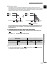
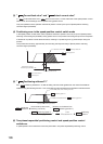
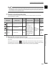
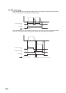
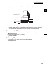
(9) Operation of speed control
Operation can stay as speed control in the speed-position control switch mode when one of the following
conditions is satisfied.
• Not to input Speed-position switching command signal (CHANGE)
• Not to turn on Speed-position switching enable signal (Y2C)
During speed control, the stroke limit function cannot be used since " Current feed value" is not updated. A
stroke range is from the lower limit switch (RLS) to the upper limit switch (FLS).
Setting item Setting range
Default
value
Setting condition
Check timing of
the set data
Buffer
memory
address
(decimal)
New speed-position
movement amount
1 to
2147483647pulse
0pulse
The data can be set when
BUSY signal (X14) is on
during speed control, and
besides before the input of
Speed-position switching
command signal (CHANGE).
At the input of
Speed-position
switching command
signal (CHANGE)
88
89
t
v
Speed control Position control
OFF
ON
P1 P2
Movement amount
can be changed
Movement amount cannot
be changed
0
Movement amount (P1) set to "
New speed-position movement amount"
Cd.6
Speed-position switching
command signal (CHANGE)
Cd.6
New speed-position
movement amount
The change after Speed-position switching
command signal (CHANGE) was turned on
is ignored.
P1 becomes the movement amount in position control.
Cd.6
Cd.6
Cd.6
Da.2
Md.1