


216
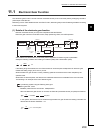
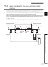
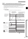
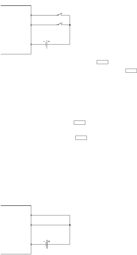
(2) Wiring upper limit switch (FLS) and lower limit switch (RLS)
To use the upper limit switch (FLS)/lower limit switch (RLS) function, wire the QD73A1's terminals for Upper limit
signal (FLS) and Lower limit signal (RLS) as in the following figure.
When wiring the terminals, set the switch that is placed on the direction in which " Current feed value"
increases as an upper limit switch (FLS), and the switch that is placed on the direction in which " Current
feed value" decreases as a lower limit switch (RLS).
If the upper and lower limit switches are wired opposite, the upper limit switch (FLS)/lower limit switch (RLS)
function does not operate normally, and the motor does not stop.
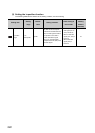
(3) Precautions for control
• OPR control, major positioning control, and JOG operation cannot be started from the area where the upper
limit switch (FLS) had detected overrange in the direction where " Current feed value" increases. Also,
OPR control, major positioning control, and JOG operation cannot be started from the area where the lower
limit switch (RLS) had detected overrange in the direction where " Current feed value" decreases. To
start operation again, move the workpiece to a position within the control range of the QD73A1 using JOG
operation.
• If the wiring between Upper limit signal (FLS) and COM terminal or between Lower limit signal (RLS) and
COM terminal is open (including the case that the terminals are not wired), the QD73A1 cannot execute
positioning.
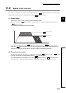
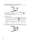
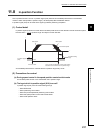
(4) When the upper limit switch (FLS)/lower limit switch (RLS) function is not used
Wire the QD73A1's terminals for Upper limit signal (FLS) and Lower limit signal (RLS) as in the following figure.
FLS
RLS
COM
24VDC
QD73A1
Md.1
Md.1
Md.1
Md.1
QD73A1
FLS
RLS
COM
24VDC