


85
CHAPTER 5 DATA USED FOR POSITIONING
5
5.5 Monitor Data
5.5 Monitor Data
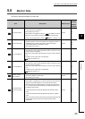
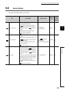
This section describes the details of monitor data.
Item Description Default value
Buffer
memory
address
(decimal)
Current feed value
• The current commanded position is stored. (different from the actual
motor position during operation)
• The update cycle is 0.5ms.
• When OPR is completed, the value of " OP address" is stored.
• When the current value is changed with the current value change
function, the changed value is stored. ( Page 217, Section 11.5)
0pulse
100
101
Actual current value
• The actual servomotor movement amount calculated based on
feedback pulses is stored as an actual current value (the number of
feedback pulses). (Actual current value = Current feed value -
Accumulated pulses in the deviation counter)
• The update cycle is 0.5ms.
0pulse
102
103
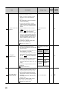
Error code (ERR.1)
• When a minor error occurs, the corresponding error code is stored.
• The latest error code is stored at all times. (When a new error occurs,
the error code is overwritten.)
• When Error reset signal (Y28) is turned on, the error code is cleared
to 0.
For details on error codes, refer to the following.
Page 250, Section 14.3
0104
Error code (ERR.2)
• When a major error occurs, the corresponding error code is stored.
• The latest error code is stored at all times. (When a new error occurs,
the error code is overwritten.)
• When Error reset signal (Y28) is turned on, the error code is cleared
to 0.
For details on error codes, refer to the following.
Page 250, Section 14.3
0105
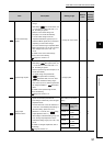
Deviation counter
value (address)
• The difference of the current feed value and actual current value is
stored as a deviation counter value.
• The update cycle is 0.5ms.
0pulse
106
107
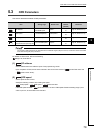
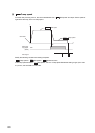
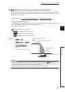
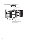
Movement amount
after near-point dog
ON
• When OPR starts, "0" is stored.
• When OPR is completed, the movement amount from the near-point
dog ON to the OPR completion is stored. (Movement amount:
Movement amount to OPR completion using near-point dog ON as
"0".) The stored value varies depending on feedback pulses input at
the OPR as shown below.
When the phase A proceeds 90 degrees than phase B: positive
value
When the phase B proceeds 90 degrees than phase A: negative
value
• The count value is stored for both the near-point dog method and the
count method. (Use the value as a reference value for OPR
adjustment.)
0pulse
108
109
Md.1
Pr.10
Md.2
Md.3
Md.4
Md.5
Md.6