


66
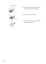
4.6.2 Precautions when connecting an encoder
This section describes precautions when connecting an encoder.
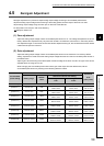
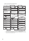
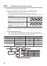
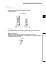
(1) Operation of the QD73A1 (deviation counter and feedback pulses)
The deviation counter in the QD73A1 counts up and down.
An addition/subtraction switchover can be processed through the phases of feedback pulses.
When "0: Positive voltage is output when the positioning address increases." is set for "Rotation direction setting"
in the switch setting.
If the sequence of the phase A and phase B is reversed, the number of command pulses and feedback pulses
are counted together. This can cause an excessive error of accumulated pulses, resulting in the stop of the
control.
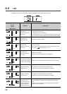
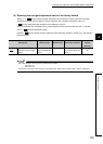
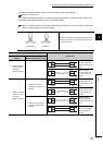
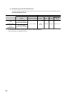
(a) Switch setting and the encoder
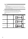
When "1: Negative voltage is output when the positioning address increases." is set for "Rotation direction
setting" in the switch setting, the count process (positive or negative) of the feedback pulses varies depending
on "Feed back pulse addition/subtraction setting" of the switch setting as shown below.
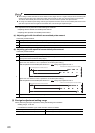
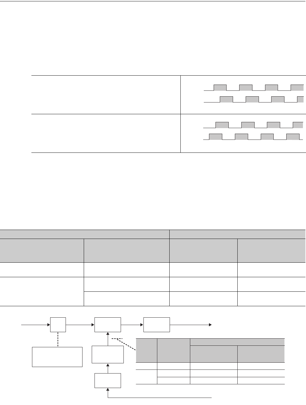
When feedback pulses are input with the phase A leading the
phase B by 90°, the number of command pulses is subtracted.
This input method is for counting positive command pulses when
the speed command is positive voltage (when the motor is rotating
forward).
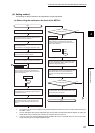
When feedback pulses are input with the phase B leading the
phase A by 90°, the number of command pulses is added.
This input method is for counting negative command pulses when
the speed command is negative voltage (when the motor is
rotating reverse).
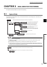
Switch setting Feedback pulse
"Rotation direction setting"
"Feed back pulse
addition/subtraction setting"
When the phase A
proceeds 90 degrees than
phase B
When the phase B
proceeds 90 degrees than
phase A
0: Positive voltage is output when the
positioning address increases.
- Subtraction Addition
1: Negative voltage is output when the
positioning address increases.
0: Add when the phase A proceeds 90
degrees than phase B.
Addition Subtraction
1: Subtract when the phase A proceeds
90 degrees than phase B.
Subtraction Addition
Phase A
Phase B
Phase A
Phase B
Deviation
counter
D/A
converter
Feedback pulse
× DIR
Command
pulse
Rotation direction setting
When 0 is set: DIR = 1
When 1 is set: DIR = -1
+
+/-
Multiplication
setting
Analog voltage
Feedback pulse
addition/
subtraction setting
Rotation
direction
setting
Feedback
pulse addition
/subtraction
setting
00
1
1
0
Feedback pulse
When the phase A
proceeds 90 degrees
than phase B
When the phase B
proceeds 90 degrees
than phase A
- (subtraction) + (addition)
+ (addition) - (subtraction)
- (subtraction) + (addition)