


277
APPENDICES
A
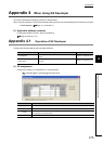
Appendix 4 When Using GX Developer
Appendix 4.1 Operation of GX Developer
*1 When setting values (values in b7 to b4 of Switch 1) are 1111
H
to 1001
H
, the setting becomes the same as the one for
the default value (0000
H
)
*2 The setting becomes enabled only when "1: Negative voltage is output when the positioning address increases." is set
for "Rotation direction setting" of Switch 1. When "0: Positive voltage is output when the positioning address increases."
is set, the setting value of "Feedback pulse addition/subtraction setting" is ignored.
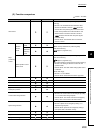
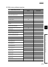
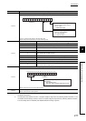
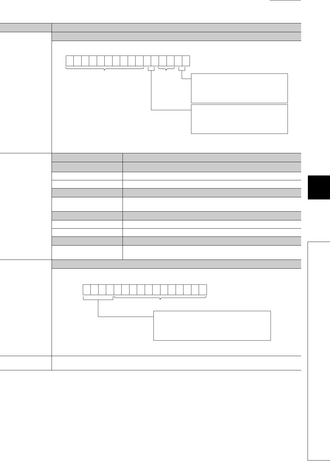
Item Setting detail
Switch 2
Encoder I/F setting and Analog voltage resolution setting
"00 or 01" means that the setting is valid with either value.
When a value is set in b15 to b6, b3, or b2, the value is ignored.
Switch 3
Bit Setting detail
b0
Feedback pulse addition/subtraction setting
*2
0 Add when the phase A proceeds 90 degrees than phase B.
1 Subtract when the phase A proceeds 90 degrees than phase B.
b3 to b1 -
0
Fixed to 0 (Empty)
When a value is set, the value is ignored.
b4 Deviation counter clear setting
0 Clear the deviation counter when Servo READY signal turns off.
1 Do not clear the deviation counter when Servo READY signal turns off.
b15 to b5 -
0
Fixed to 0 (Empty)
When a value is set, the value is ignored.
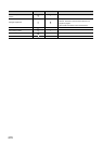
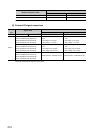
Switch 4
Zero/gain adjustment mode/Normal mode setting
When a value is set in b11 to b0, the value is ignored.
Switch 5
Fixed to 0 (Empty)
When a value is set, the value is ignored.
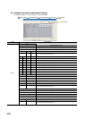
b15b14b13b12b11b10 b9 b8 b7 b6 b5 b4 b3 b2 b1 b0
Fixed to 0 Fixed to 0
0000000000 00
b1 and b0: Encoder I/F setting
00 or 01: Open collector output
10: TTL output
11: Differential output
b5 and b4: Analog voltage resolution setting
00 or 01: 12-bit resolution
10: 14-bit resolution
11: 16-bit resolution
b15b14b13b12b11b10 b9 b8 b7 b6 b5 b4 b3 b2 b1 b0
b15 to b12: Zero/gain adjustment mode/Normal
mode setting
0000: Normal mode
Other than 0000: Zero/gain adjustment mode
Fixed to 0
000000000000