


30
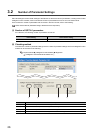
3.4 I/O Signals from/to the CPU Module
This section describes I/O signals of the QD73A1.
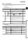
3.4.1 I/O signal list
This section describes I/O signal assignment and use of each signal.
The first half of the I/O assignment is empty 16 points, and the second half is intelligent 32 points. When the module is
mounted on the slot No.0 and 1 of a main base unit, the device No.Xn0 becomes X10. Although, when the slot No.0 is
set as empty 0 point in the I/O assignment setting of GX Works2, the device No.Xn0 becomes X0 (n=0).
Device numbers used in this manual are for the case when the QD73A1 is mounted on the slot No.0 and 1 and when
the slot No.0 is empty 16 points.
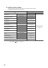
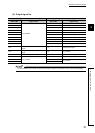
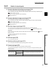
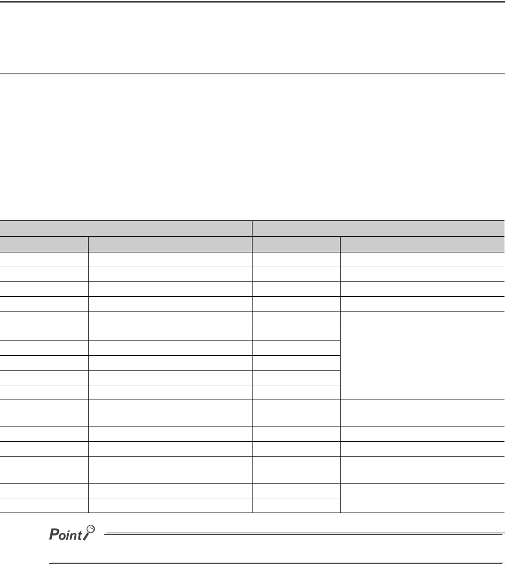
(1) Input signal list
If a "Use prohibited" area is turned on/off through a sequence program, the QD73A1's function cannot be guaranteed.
Input signal (CPU module QD73A1) Input signal (CPU module QD73A1)
Device No. Signal name Device No. Signal name
X10 WDT error, H/W error signal X20 OPR start complete signal
X11 QD73A1 READY signal X21 Absolute positioning start complete signal
X12 OPR request signal X22 Forward start complete signal
X13 OPR complete signal X23 Reverse start complete signal
X14 BUSY signal X24 Synchronization flag
X15 Positioning complete signal X25
Use prohibited
X16 In-position signal X26
X17 Excessive error signal X27
X18 Error detection signal X28
X19 Overflow signal X29
X1A Underflow signal X2A
Zero/gain adjustment data writing complete
flag
X1B Servo READY signal X2B Zero/gain adjustment change complete flag
X1C Near-point dog signal X2C Set value change complete flag
X1D External stop signal X2D
Operating status of the speed-position
control switch mode
X1E Upper limit signal X2E
Use prohibited
X1F Lower limit signal X2F