


71
CHAPTER 4 SETTINGS AND PROCEDURE BEFORE OPERATION
4
4.6 Wiring
4.6.3 External device connectors
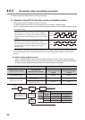
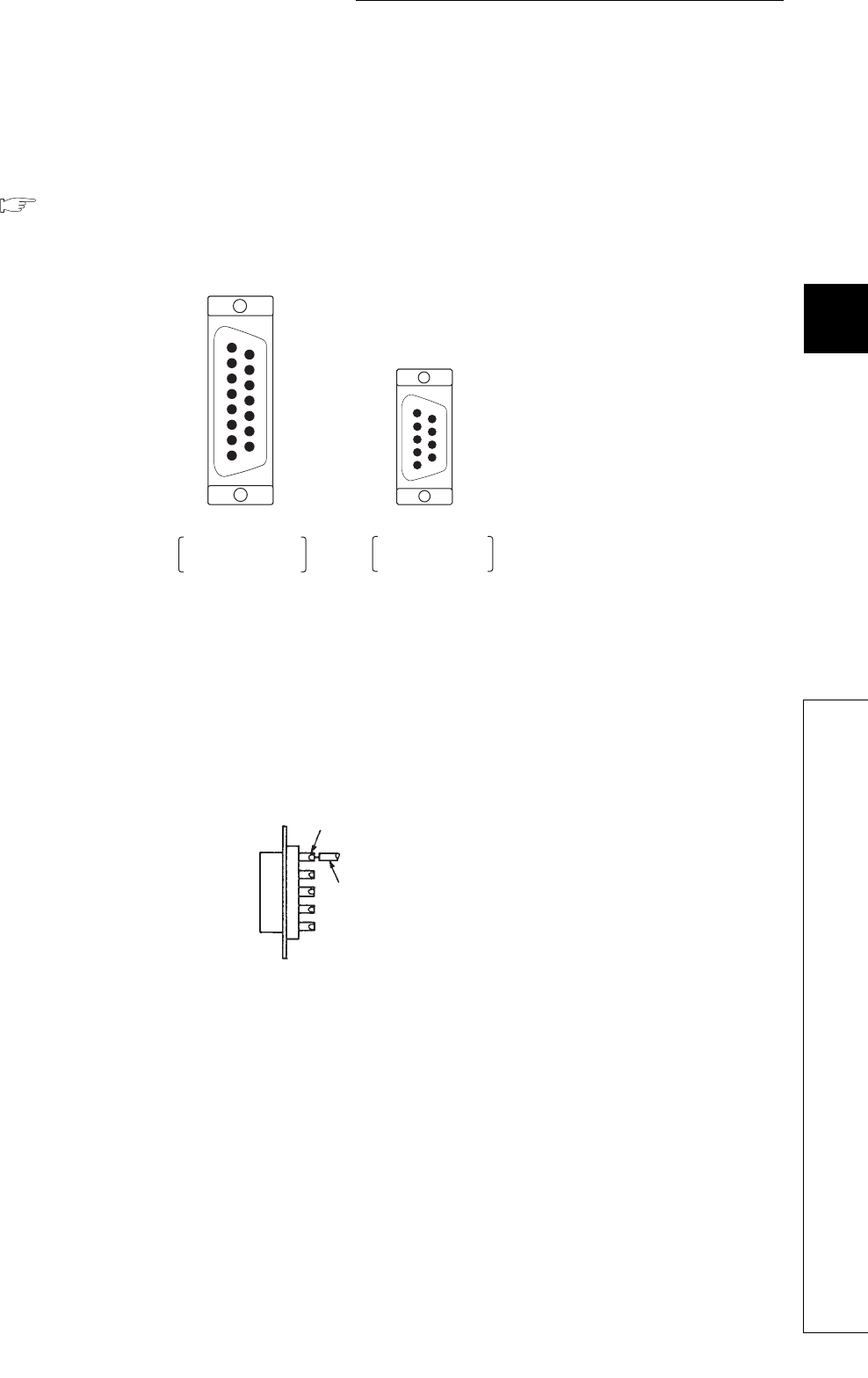
(2) Wiring connectors
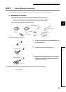
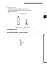
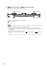
The figure below shows the pin arrangement on the connectors.
Wire pins correctly according to the signal assigned to each pin number.
For details on the signal assigned to each pin number, refer to the following.
Page 43, Section 3.5.3
(a) Applicable wire size
The applicable wire size is 0.3mm
2
or less. If thicker wires are used, the wire clamp cannot be attached.
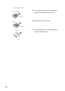
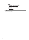
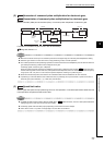
(b) Connection between the connectors and wires
Solder the wires to the pins.
Strip parts of wire jackets properly to avoid a short circuit due to wire chips or solder chips.
If the signal line is exposed, malfunction may occur due to static electricity. Cover and protect the connector
pins with heat shrinkable insulation tubes.
9
1
2
3
4
5
6
7
8
12
1
2
3
4
5
9
10
11
15
6
7
8
13
14
9-pin connector
Applies to the
CONT. connector
15-pin connector
Applies to the
SERVO. connector
Pin arrangement viewed
from the wire side
Soldering
Wire