


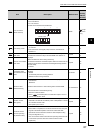

90
Deviation counter clear
command
• Use this area to clear the accumulated
pulses in the deviation counter.
• Write "1" to clear the counter. If a value
other than "1" is set, the command is
ignored.
• After the deviation counter was cleared, "0"
is stored automatically.
• To start positioning after the deviation
counter was cleared, check that this area
stores "0" and no error is detected before
the start.
• When the deviation counter is cleared,
" Actual current value" changes to the
value in " Current feed value".
• Data cannot be written while BUSY signal
(X14) is on. Check that BUSY signal (X14)
is off before writing data. If data writing is
attempted while BUSY signal (X14) is on,
the error "Deviation counter clear error"
(error code: 114) occurs.
For details on the deviation counter clear
function, refer to the following.
Page 220, Section 11.7
1: Clear the deviation
counter
086
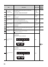
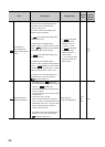
Analog output
adjustment area 1
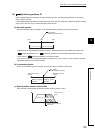
• Set pulse amount to adjust gain with
specific accumulated pulse amount.
• This setting is enabled only in the zero/gain
adjustment mode.
• Use this area when the default value or one
of the selections 1 to 4 is set in
"Accumulated pulse setting" in the switch
setting. (When one of the selections 5 to 8 is
set, use " Analog output adjustment
area 2".)
• If the setting is outside the setting range, the
error "Analog output adjustment area 1
Outside the setting range" (error code: 125)
occurs.
For details on zero/gain adjustment, refer to
the following.
Page 59, Section 4.5
Depends on "Accumulated
pulse setting" in the switch
setting.
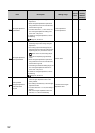
087
Accumulated
pulse setting
Setting
range (Unit:
pulse)
Selection 1
-3700 to
3700
Selection 2
-7400 to
7400
Selection 3
-11100 to
11100
Default value
or selection
4
-14800 to
14800
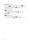
New speed-position
movement amount
• Set this area to change movement amount
of after a switchover to position control in
the speed-position control switch mode.
• The set value is reflected at the input of
Speed-position switching command signal
(CHANGE).
• The setting is cleared to 0 when the next
operation starts.
For details on the Speed-position control
switch mode, refer to the following.
Page 195, Section 9.6.2
1 to 2147483647pulse 0pulse
88
89
Item Description Setting range
Default
value
Buffer
memory
address
(decimal)
Cd.4
Md.2
Md.1
Cd.5
Cd.9
Cd.6