


40
3.5 Specifications of I/O Interfaces with External Devices
This section describes I/O interfaces between the QD73A1 and external devices.
3.5.1 Electrical specifications of I/O signals
This section describes electrical specifications of I/O interfaces between the QD73A1 and external devices.
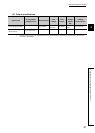
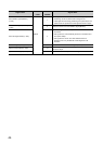
(1) Input specifications
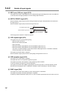
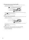
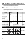
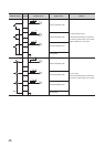
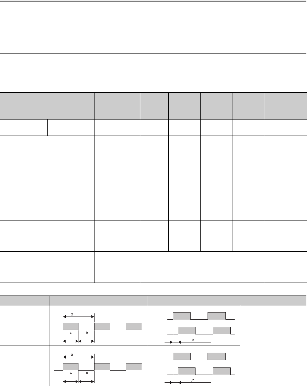
*1 The following table shows the pulse width and phase difference depending on pulse frequency.
Signal name
Voltage
range/Current
consumption
ON
voltage
ON
current
OFF
voltage
OFF
current
Pulse
frequency
Supply power Input common
5 to 24VDC/
Max.60mA
Servo READY signal (READY)
Stop signal (STOP)
Near-point dog signal (DOG)
Upper limit signal (FLS)
Lower limit signal (RLS)
Speed-position switching command
signal (CHANGE)
4.75 to 26.4VDC
3V or
higher
2.5mA or
higher
1V or lower
0.1mA or
lower
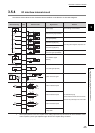
(Open collector method)
Phase-A feedback pulse (PULSE A)
Phase-B feedback pulse (PULSE B)
Phase-Z feedback pulse (PULSE Z)
10.8 to 14VDC
4V or
higher
2.7mA or
higher
1V or lower
0.1mA or
lower
200kpulse/s or
less
*1
(TTL method)
Phase-A feedback pulse (PULSE A)
Phase-B feedback pulse (PULSE B)
Phase-Z feedback pulse (PULSE Z)
4.5 to 5.5VDC
2.8V or
higher
0.8V or
lower
200kpulse/s or
less
*1
(Differential output method)
Phase-A feedback pulse (PULSE A)
Phase-B feedback pulse (PULSE B)
Phase-Z feedback pulse (PULSE Z)
EIA standard
RS-422-A differential line receiver
(Equivalent of AM26LS32 (Manufactured by Texas
Instruments Inc.))
1Mpulse/s or
less
*1
Pulse frequency Pulse width (duty ratio: 50%) Phase difference
200kpulse/s or less
When the phase A leads the
phase B, the positioning
address (current value)
increases.
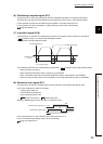
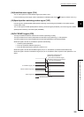
1Mpulse/s or less
5 s or more
2.5 s
or more
2.5 s
or more
Phase A
Phase B
1.25 s or more
1 s or more
0.5 s
or more
0.5 s
or more
Phase A
Phase B
0.25 s or more