


215
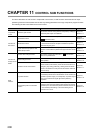
CHAPTER 11 CONTROL SUB FUNCTIONS
11
11.4 Upper Limit Switch (FLS)/Lower Limit Switch (RLS) Function
11.4 Upper Limit Switch (FLS)/Lower Limit Switch (RLS)
Function
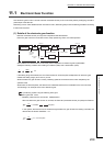
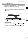
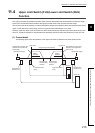
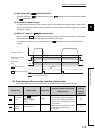
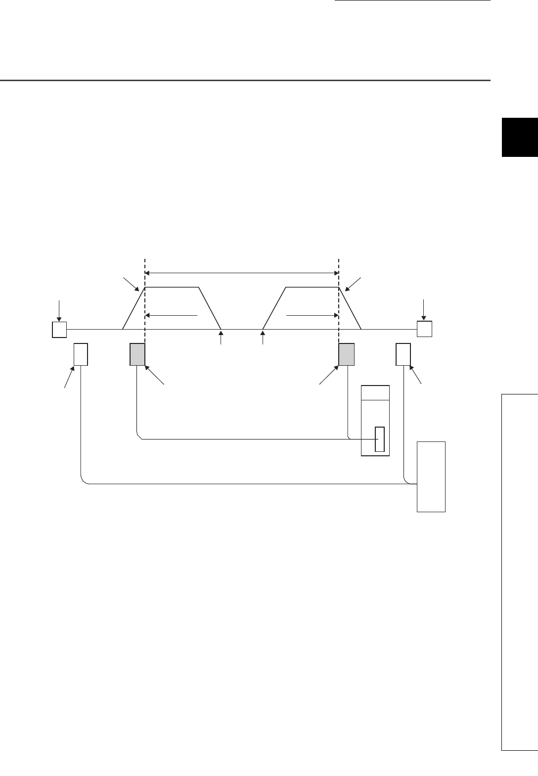
The "upper limit switch (FLS)/lower limit switch (RLS) function" decelerates and stops operation according to signal
inputs from limit switches that are placed at the upper and lower limits of the machine's movable range.
This function prevents the machine from being damaged by stopping the operation before the workpiece reaches the
upper or lower limit of the moving range, which is a physical limit that the QD73A1 can handle.
Normally, upper limit switch (FLS) and lower limit switch (RLS) are placed inside the stroke limits (stroke ends) of the
drive unit, so that the operation is stopped before the workpiece reaches a stroke limit (stroke end) of the drive unit.
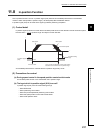
(1) Control detail
The following figure shows the operation of the upper limit switch (FLS)/lower limit switch (RLS) function.
Decelerates and stops upon
detection of the lower limit
switch (RLS)
Decelerates and stops upon
detection of the upper limit
switch (FLS)
Lower limit switch
(RLS)
Upper limit switch
(FLS)
Stroke limit of
the drive unit
Stroke limit of
the drive unit
Drive unit
Mechanical stopper Mechanical stopper
Starts toward
the lower limit
direction
Starts toward
the upper limit
direction
Moving
direction
Moving
direction
Control range of the QD73A1
Lower limit Upper limit
QD73A1