


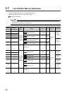
56
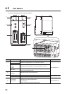
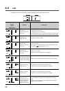
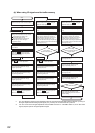
4.3 Part Names
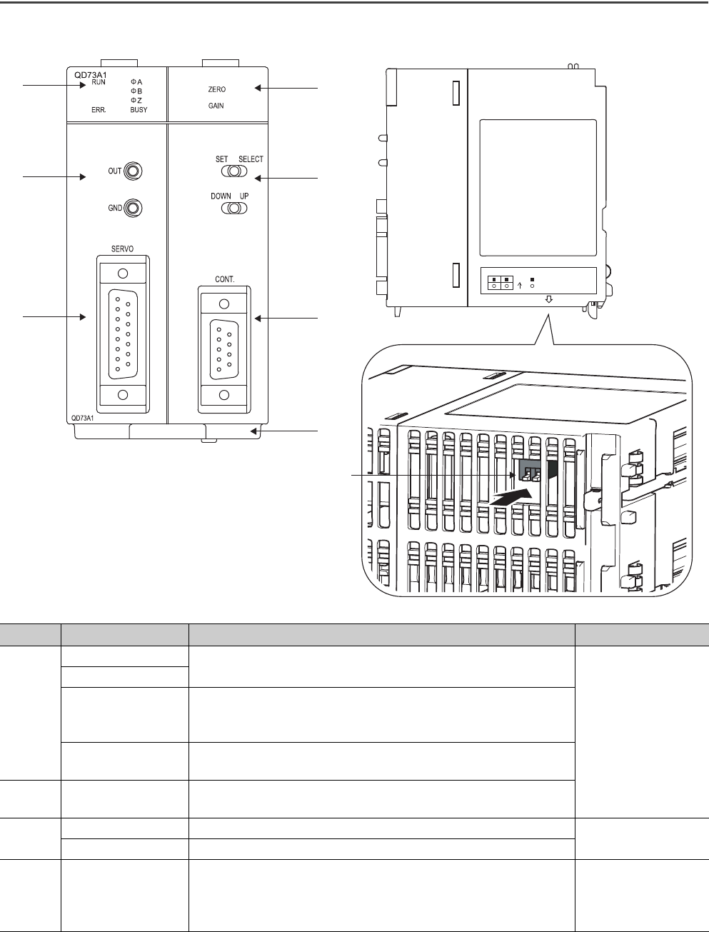
This section describes the part names of the QD73A1.
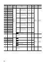
Number Name Description Reference
1)
RUN LED
Indicates the operating status or error status of the QD73A1
Page 58, Section 4.4
ERR. LED
A LED
B LED
Z LED
Indicates the status of pulses on an encoder input phase A, B, or Z
BUSY LED
Indicates the status of BUSY signal (X14) or writing of zero adjustment
value and gain adjustment value
2)
ZERO LED
GAIN LED
Indicates the status of zero/gain adjustment
3)
SELECT/SET switch A switch for zero adjustment and gain adjustment
Page 61, Section 4.5 (4)
UP/DOWN switch A switch to adjust an analog output voltage value
4)
OUT terminal
GND terminal
Check pins to measure analog output voltage
(Use these pins for zero/gain adjustment.)
[Inside diameter]
2.03mm for both OUT terminal and GND terminal
Page 59, Section 4.5
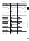
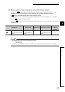
1)
4)
5)
2)
3)
6)
7)
8)
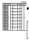
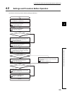
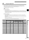
21
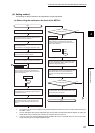
ON ADJUSTMENT MODE
NORMAL MODE