


68
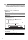
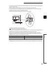
● If the connection of the QD73A1 and the encoder is incorrect, the motor rotates at a power-on and Excessive error signal
(X17) turns on.
● To replace the positioning module AD70/A1SD70 with the QD73A1 while using the same equipment of the servo
amplifier, encoder, and external wiring in the existing system, check the setting of slide switch 1 (rotation direction
setting) of the AD70/A1SD70.
If the slide switch 1 (rotation direction setting) is off ("Negative voltage is output when the positioning address increases"
is set), set "1: Subtract when the phase A proceeds 90 degrees than phase B." for "Feed back pulse addition/subtraction
setting" in the switch setting of the QD73A1.
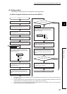
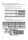
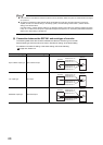
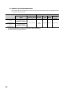
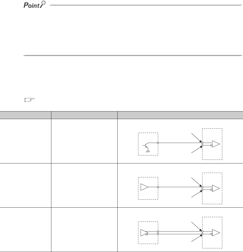
(2) Connection between the QD73A1 and each type of encoder
The following table shows the connection between the QD73A1 and each type of encoder.
Set the output type of the encoder to be used in "Encoder I/F setting" of the switch setting.
For details on "Encoder I/F setting" in the switch setting, refer to the following.
Page 100, Section 6.2
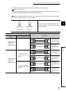
Encoder output type "Encoder I/F setting" Connection
Open collector output type Open collector output
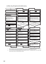
TTL output type TTL output
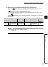
Differential output type Differential output
Phase A: Pin 13
Phase B: Pin 5
Phase Z: Pin 6
Phase A: Pin 11
Phase B: Pin 10
Phase Z: Pin 7
Encoder
QD73A1
Phase A: Pin 13
Phase B: Pin 5
Phase Z: Pin 6
Phase A: Pin 11
Phase B: Pin 10
Phase Z: Pin 7
Encoder
QD73A1
Phase A: Pin 13
Phase B: Pin 5
Phase Z: Pin 6
Phase A: Pin 11
Phase B: Pin 10
Phase Z: Pin 7
Encoder
QD73A1
SN75113