


214
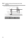
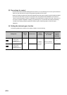
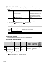
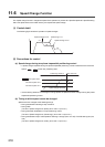
(2) Stroke limit check details and processing for each control
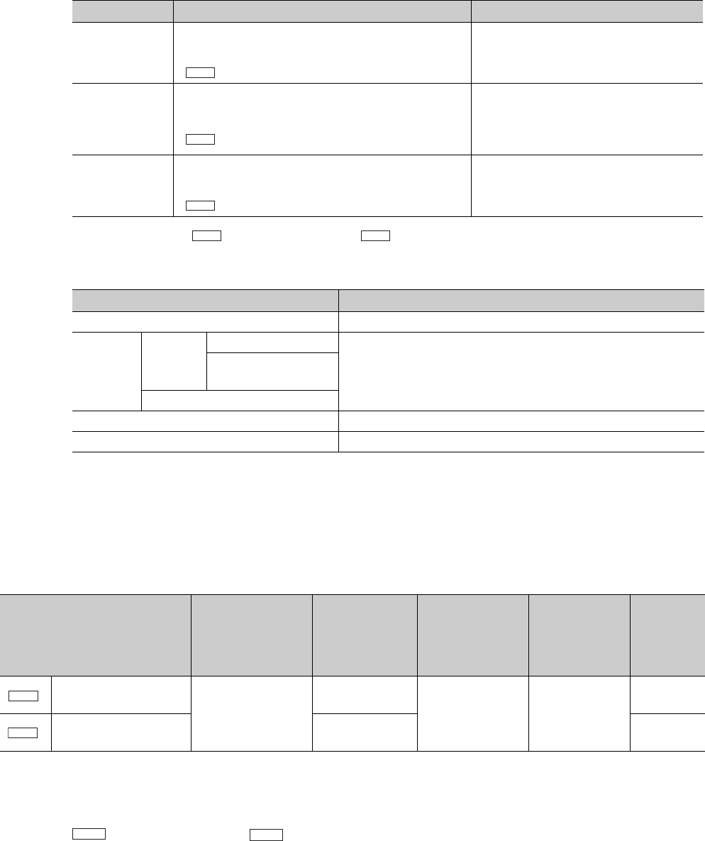
The following table describes stroke limit checks and processing in case of an error that are performed by the
QD73A1.
*1 The range from " Stroke limit upper limit" to " Stroke limit lower limit"
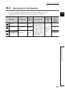
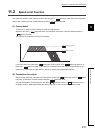
The following table describes the corresponding stroke limit check for each control.
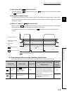
(3) Precaution for control
To execute the stroke limit function normally, OPR must be executed beforehand.
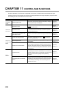
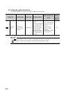
(4) Setting the stroke limit function
The following table lists the data to be set, setting condition, and check timing.
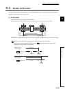
(5) Disabling the stroke limit function
Set values as follows.
Stroke limit upper limit = Stroke limit lower limit
Check number Check detail Processing in case of an error
1
If a current value is outside the stroke limit range
*1
, the
module reports an error. (The module checks
" Current feed value".)
The module turns on Error detection signal
(X18), and reports the error "Outside the
stroke limit range at start" (error code: 83).
2
If a positioning address setting is outside the stroke limit
range
*1
, the module reports an error. (The module checks
" Positioning address P1".)
The module turns on Error detection signal
(X18), and reports the error "Positioning
address Outside the setting range" (error
code: 30).
3
If a current value exceeds the stroke limit range
*1
, the
module reports an error. (The module checks
" Current feed value".)
The module turns on Error detection signal
(X18), and reports the error "Outside the
stroke limit range" (error code: 100).
Control Stroke limit check
OPR control Stroke limit check 3 is performed.
Major
positioning
control
Position
control
mode
Positioning control
Stroke limit check 1 and 2 are performed.
Two-phase trapezoidal
positioning control
Speed-position control switch mode
JOG operation Stroke limit check 3 is performed.
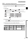
Current value change No stroke limit check is performed.
Setting item Setting range Default value
Setting
condition
Check timing
of the set data
Buffer
memory
address
(decimal)
Stroke limit upper limit
-2147483648 to
2147483647 pulse
2147483647
pulse
PLC READY signal
(Y2D) must be off.
When PLC
READY signal
(Y2D) is turned
on
0
1
Stroke limit lower limit 0pulse
2
3
Md.1
Da.2
Md.1
Pr.1
Pr.2
Pr.1
Pr.2
Pr.1
Pr.2