65
CHAPTER 4 SETTINGS AND PROCEDURE BEFORE OPERATION
4
4.6 Wiring
4.6.1 Wiring precautions
• As a measure against noise, use shielded cables if the cables connected to the module are close (less than
100mm) to a power cable.
Ground the shields of shielded cables to the control panel securely on the module side.
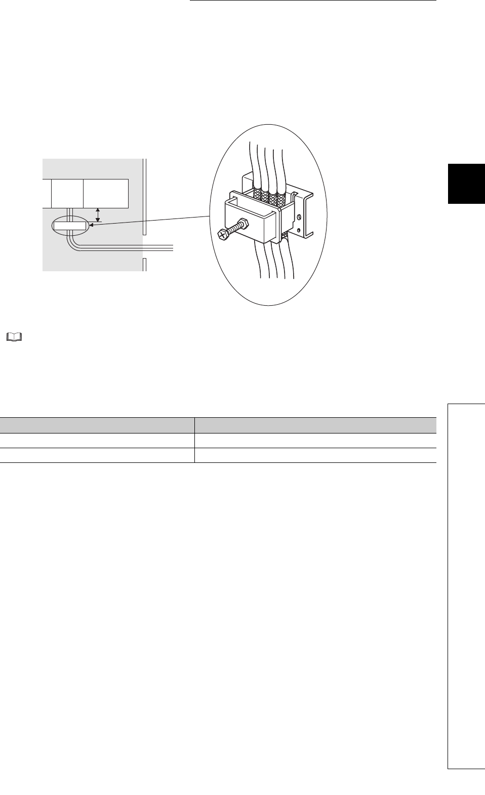
• To comply with EMC and Low Voltage Directives, ground shielded cables to the control panel using the
AD75CK cable clamp (manufactured by Mitsubishi Electric).
(Ground the shield parts at a point within 20 to 30cm from the module.)
For details on the AD75CK, refer to the following.
AD75CK-type Cable Clamping Instruction Manual
• The length of the cable between the module and the drive unit is 1 to 3m generally. The length depends on
the specifications of the drive unit. Review the specifications of the drive unit to be used.
• The length of the cable between the module and the encoder is as listed below generally. The length
depends on the specifications of the encoder. Review the specifications of the encoder to be used. Use
shielded twisted pair cable for the connection with the encoder.
• Connect the module and Servo ON signal of the drive unit without fail. In addition, do not turn on/off Servo
ON signal externally. If Servo ON signal is not connected, the motor may rotate even in case of a CPU error.
Encoder output type Cable length
Differential output type MAX. 30m
TTL type, open collector type MAX. 3m
20 to 30cm
Inside the control panel
AD75CK
QD73A1


