


69
CHAPTER 4 SETTINGS AND PROCEDURE BEFORE OPERATION
4
4.6 Wiring
4.6.3 External device connectors
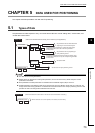
4.6.3 External device connectors
This section describes the assemblage of an external device connector and its connection method.
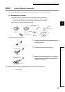
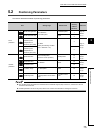
(1) Assembling a connector
The following connectors are required to connect the QD73A1 and external devices.
• A 9-pin connector (pin type): For the CONT. connector (control signal connection)
• A 15-pin connector (pin type): For the SERVO connector (drive unit connection)
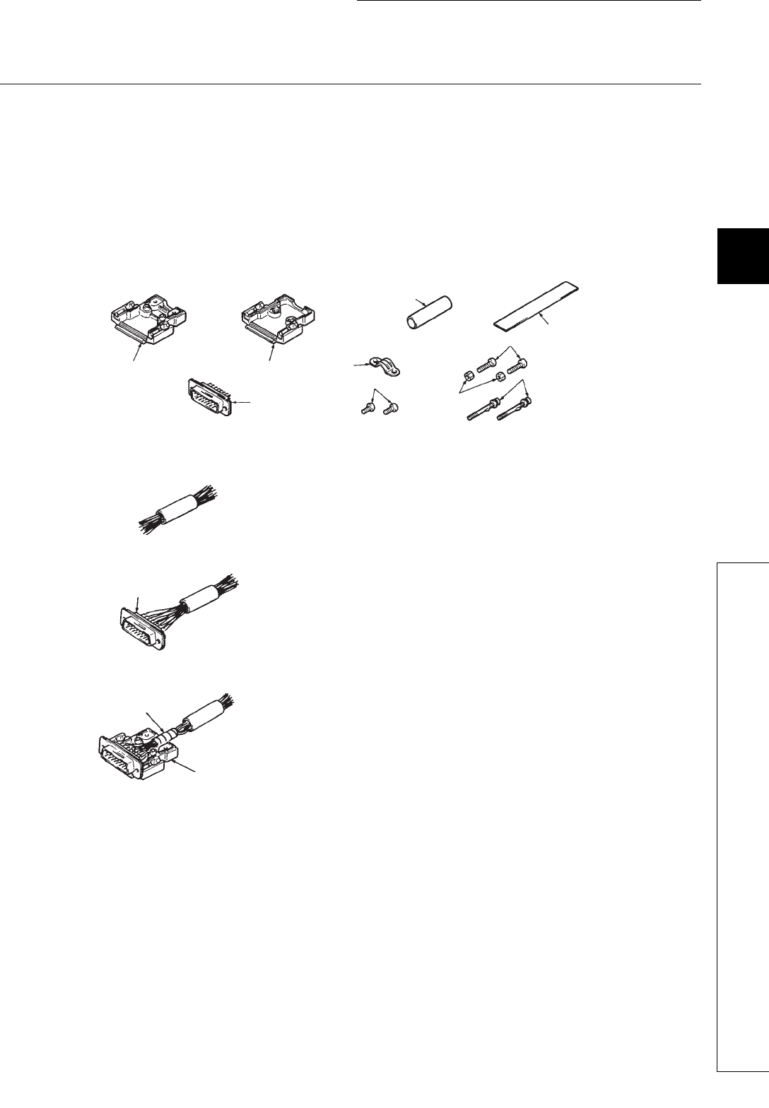
The connectors are composed of the following parts.
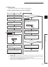
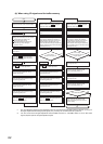
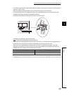
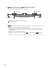
Assemble the connectors as follows.
1. Thread wires through the protection tube (for the 15-
pin connector only).
2. Solder the wires to the connection part.
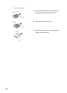
3. Attach the connection part to cover A, and wrap the
protective seal around the part of the wires which
contacts the wire clamp.
4. Slide the protection tube over the protective seal (for the 15-pin connector only).
(To the next page)
Cover A Cover B
Wire clamp
Protective seal
Connection part
Screw A
Screw B
Screw C
Nut
Protective tube
(For a 15-pin connector only)
Connection part
Wrap the wires with
a protective seal.
Cover A