


201
CHAPTER 10 JOG OPERATION
10
10.1 Operation of JOG Operation
10.1 Operation of JOG Operation
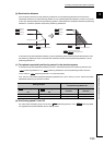
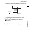
Once JOG speed is set and while a JOG start signal is turned on through a sequence program, the QD73A1 executes
JOG operation in the specified direction by outputting analog voltage to the drive unit.
Choose forward run or reverse run using JOG start signals.
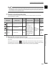
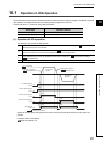
(1) Operation of JOG operation
The following is an example of JOG operation.
Speed can be changed by writing data to the control change area of the buffer memory using a sequence
program.
For details, refer to the following.
Page 218, Section 11.6
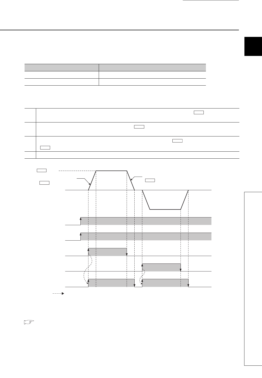
Start signal Operation direction
Forward JOG start signal (Y24) Address increasing direction
Reverse JOG start signal (Y25) Address decreasing direction
1
As a JOG start signal is turned on, acceleration starts in the specified direction according to " Acceleration time".
BUSY signal (X14) turns on at this time.
2
As the accelerating operation reaches the speed set in " JOG speed", the move continues maintaining the
speed. The workpiece moves at the constant speed between 2 to 3 in the graph below.
3
As the JOG start signal is turned off, deceleration starts from the speed set in " JOG speed" according to
" Deceleration time".
4 As the speed reaches 0, the operation stops. BUSY signal (X14) turns off at this time.
Pr.6
Cd.3
Cd.3
Pr.7
Executed by the QD73A1
ON
ON
OFF
OFF
OFF
OFF
OFF
ON
ON
ON ON
12 34
Forward JOG
operation
Reverse JOG
operation
PLC READY signal
(Y2D)
QD73A1 READY signal
(X11)
Forward JOG start signal
(Y24)
Reverse JOG start signal
(Y25)
BUSY signal
(X14)
Deceleration according to
" Deceleration time"
Acceleration according to
" Acceleration time"
JOG speed
Cd.3
Pr.7
Pr.6