42
3.5.2 Signal layout for external device connectors
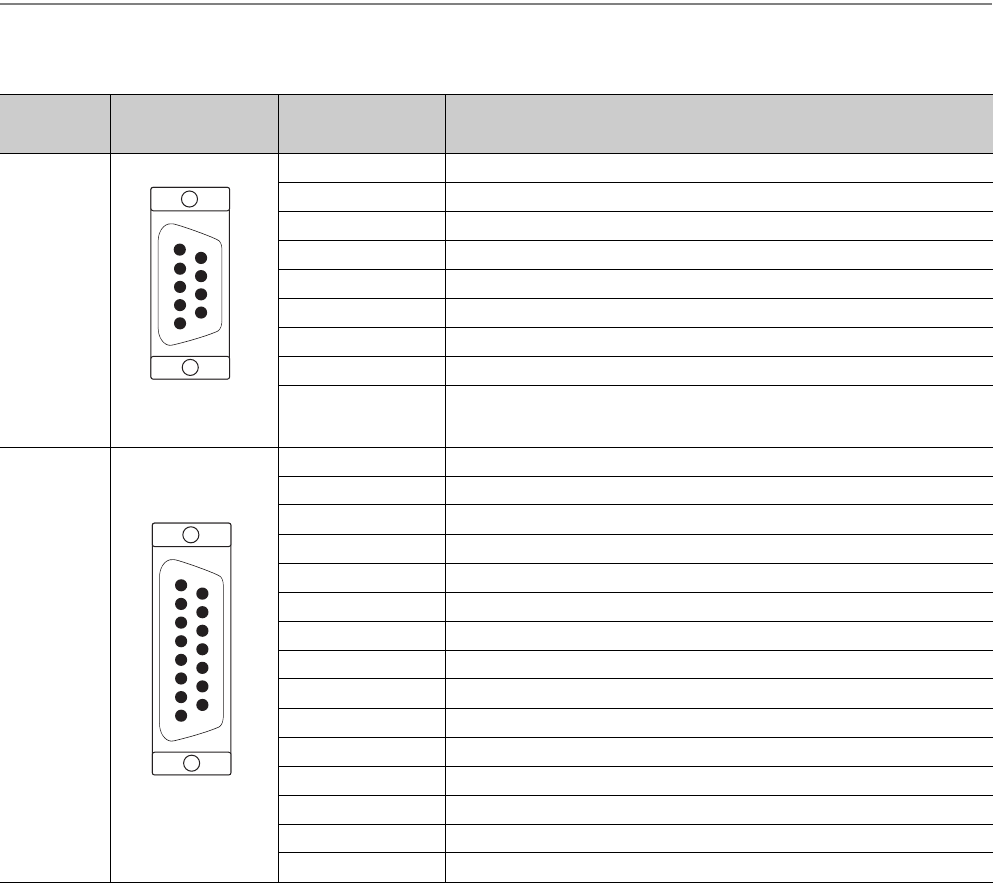
The following table shows signal layouts on external device connectors.
Connector
name
Pin arrangement Pin number Signal name
CONT.
Viewed from the front
of the module
1 Near-point dog signal (DOG)
2Empty
3Empty
4Empty
5 Power supply (5 to 24V)
6 Lower limit signal (RLS)
7 Upper limit signal (FLS)
8 Speed-position switching command signal (CHANGE)
9 Stop signal (STOP)
SERVO
Viewed from the front
of the module
1 Servo READY signal (READY) (+ side)
2 Servo READY signal (READY) (- side)
3 Servo ON signal (SVON) (+ side)
4 Servo ON signal (SVON) (- side)
5 Phase-B feedback pulse (PULSE B) (+ side)
6 Phase-Z feedback pulse (PULSE Z) (+ side)
7 Phase-Z feedback pulse (PULSE Z) (- side)
8Empty
9 Analog GND
10 Phase-B feedback pulse (PULSE B) (- side)
11 Phase-A feedback pulse (PULSE A) (- side)
12 Empty
13 Phase-A feedback pulse (PULSE A) (+ side)
14 Speed command signal (- side)
15 Speed command signal (+ side)
9
1
2
3
4
5
6
7
8
12
1
2
3
4
5
9
10
11
15
6
7
8
13
14


